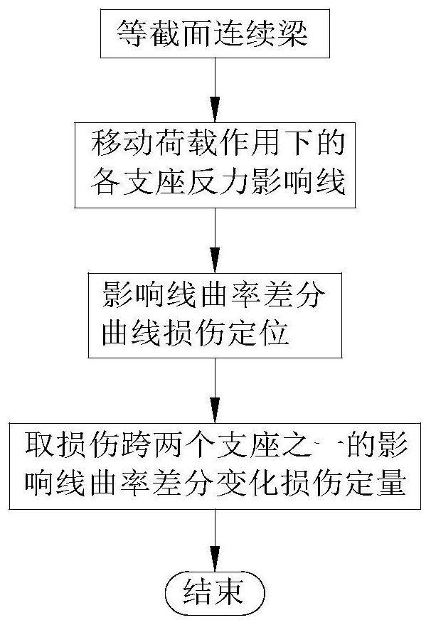
Damage identification method for constant cross-section continuous beams based on the curvature difference of support reaction forces
A technology for bearing reaction force and damage identification, which can be used in elastic testing, testing of machine/structural components, instruments, etc., and can solve problems such as inability to provide
- Summary
- Abstract
- Description
- Claims
- Application Information
AI Technical Summary
Problems solved by technology
Method used
Image
Examples
Embodiment 1
[0138] Embodiment one: see Figure 9 , the span layout of the two-span continuous beam is 50+50cm, 5cm divides a unit, and 21 nodes (the numbers in the circles in the upper row in the figure are the unit numbers, and the numbers in the lower row are the node numbers). The cross-sectional size of the plate is b×h=6cm×3cm, and the elastic modulus of the material is 2.7×10 3 MPa, the density is 1200kg / m 3 .
[0139] The damage in the actual bridge structure, such as the generation of cracks, material corrosion or the reduction of elastic modulus, generally only causes a large change in the structural stiffness, but has little impact on the quality of the structure. Therefore, in the finite element calculation, the damage of the element is simulated by reducing the elastic modulus. The beam structure model is established by finite element software. Taking the damage condition of a single unit of a two-span continuous beam as an example, considering that the 5 units in the midd...
Embodiment 2
[0151] Embodiment two: see Figure 12 , the span layout of the three-span continuous beam is 50+75+50cm, 5cm divides a unit, and 36 nodes (the numbers in the upper circle in the figure are the unit numbers, and the lower numbers are the node numbers). The cross-sectional size of the plate is b×h=6cm×3cm, and the elastic modulus of the material is 2.7×10 3 MPa, the density is 1200kg / m 3 . Considering that multiple damages of different degrees occur at the same time, the damage conditions are shown in Table 2.
[0152] Table 2 Multiple damage conditions of cantilever beam
[0153]
[0154] The specific implementation steps are as follows:
[0155] Step 1: Set measuring points at the positions of supports 1#, 2#, 3# and 4#, apply a 1kN moving load to the three-span continuous beam, and obtain the support reaction force influence line measured on the beam support.
[0156] Step 2: Calculate the curvature difference of the support reaction force influence line of each suppo...
PUM
 Abstract
Description
Claims
Application Information
 - R&D
- Intellectual Property
- Life Sciences
- Materials
- Tech Scout
- Unparalleled Data Quality
- Higher Quality Content
- 60% Fewer Hallucinations
Browse by: Latest US Patents, China's latest patents, Technical Efficacy Thesaurus, Application Domain, Technology Topic, Popular Technical Reports.
© 2025 PatSnap. All rights reserved.Legal|Privacy policy|Modern Slavery Act Transparency Statement|Sitemap|About US| Contact US: help@patsnap.com


