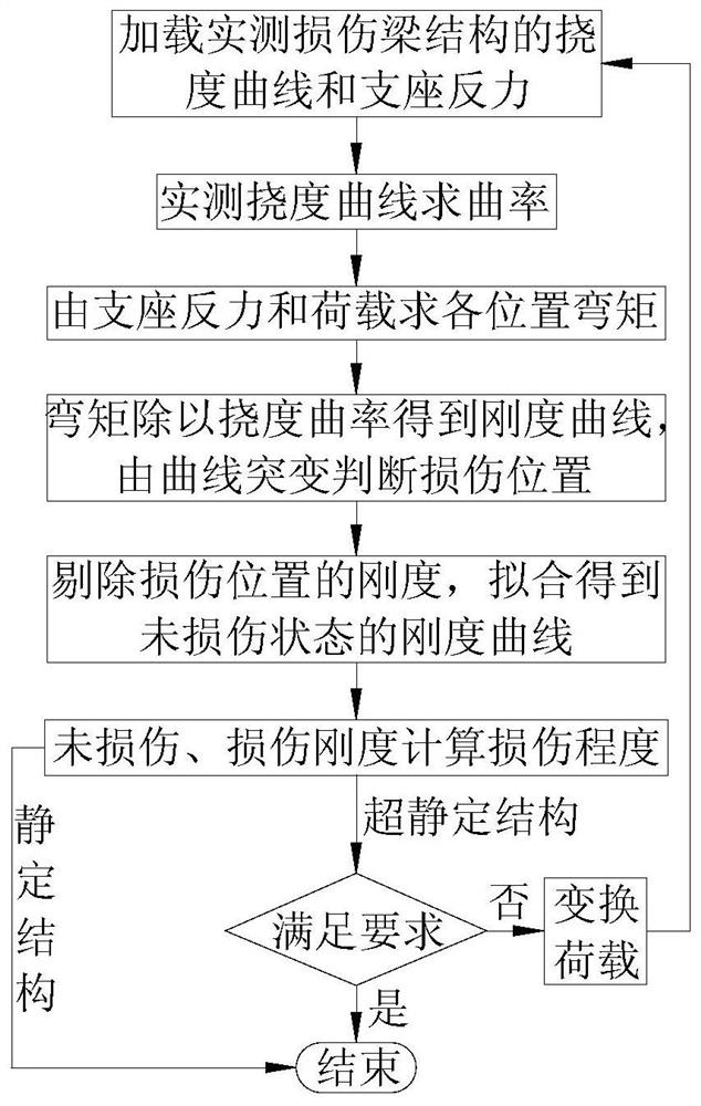
Damage identification method of beam structure based on support reaction force and deflection curvature
A support reaction force and damage identification technology, applied in the testing of machines/structural components, elastic testing, instruments, etc., can solve the problems of not being able to identify the degree of structural damage and requiring information before damage
- Summary
- Abstract
- Description
- Claims
- Application Information
AI Technical Summary
Problems solved by technology
Method used
Image
Examples
Embodiment 1
[0174]Example 1: seeFigure 17 , The span of the simply supported beam is 100cm, 5cm is divided into a unit, a total of 20 units, 21 measuring points (the numbers in the upper row of circles in the figure are the unit numbers, and the numbers in the lower row are the numbers of the measuring points). The section size of the board is b×h=4.5cm×1.5cm, and the elastic modulus of the material is 2.7×10³MPa, Poisson's ratio is 0.37, density is 1200kg / m3.
[0175]The damage in the actual engineering structure, such as the occurrence of cracks, material corrosion, or the decrease of elastic modulus, generally only causes a large change in the stiffness of the structure, and has a small effect on the quality of the structure. Therefore, in the finite element calculation, it is assumed that the structural element damage only causes the decrease of the element stiffness, but does not cause the element quality to change. The damage of the element is simulated by the decrease of the elastic modulus...
Embodiment 2
[0184]Example 2: seeFigure 22 , The cantilever beam span is 100cm, 5cm is divided into a unit, a total of 20 units, 21 measuring points (the numbers in the upper row of circles in the figure are the unit numbers, and the numbers in the lower row are the numbers of the measuring points). The section size of the board is b×h=4.5cm×1.5cm, and the elastic modulus of the material is 2.7×10³MPa, Poisson's ratio is 0.37, density is 1200kg / m3.
[0185]Considering that the fixed end unit 1, the mid-span unit 10, and the free end unit 20 have different degrees of damage together, the damage conditions are shown in Table 2.
[0186]Table 2 Multiple damage conditions of cantilever beam
[0187]
[0188]The specific implementation steps are as follows:
[0189]Step 1: Apply a concentrated load of 10N at the 21st measuring point at the cantilever end of the damaged cantilever beam to obtain the measured deflection curve of the cantilever beam after damage. The reaction force of the support is equal to the load ...
Embodiment 3
[0195]Example three: seeFigure 27 , The three-span continuous beam span is arranged as 100+150+100cm, 10cm is divided into a unit, a total of 35 units, 36 measuring points (the numbers in the upper row of circles in the figure are the unit numbers, and the numbers in the lower row are the support numbers) . The section size of the board is b×h=4.5cm×1.5cm, and the elastic modulus of the material is 2.7×10³MPa, Poisson's ratio is 0.37, density is 1200kg / m3.
[0196]Unit 7 is located near the 0 point of the side span bending moment (ie the inflection point of deflection curvature) under uniform load, unit 13 is located near the 0 point of the bending moment of the concentrated load in the middle span, unit 18 is the middle span unit, and unit 26 is the third span The maximum negative bending moment unit, the damage conditions are shown in Table 3.
[0197]Table 3 Damage conditions of three-span continuous beam
[0198]
[0199]The specific implementation steps of condition 1 are as follows:
[0200]...
PUM
 Abstract
Description
Claims
Application Information
 - R&D
- Intellectual Property
- Life Sciences
- Materials
- Tech Scout
- Unparalleled Data Quality
- Higher Quality Content
- 60% Fewer Hallucinations
Browse by: Latest US Patents, China's latest patents, Technical Efficacy Thesaurus, Application Domain, Technology Topic, Popular Technical Reports.
© 2025 PatSnap. All rights reserved.Legal|Privacy policy|Modern Slavery Act Transparency Statement|Sitemap|About US| Contact US: help@patsnap.com


