Driving wheel road holding force and life detection device and road holding force and life detection method
A detection device and driving wheel technology, applied in the direction of automobile tire testing, etc., can solve the problems of driving wheel pinning, bearing technology is not high enough, achieve the effect of pressure balance and improve fault tolerance rate
- Summary
- Abstract
- Description
- Claims
- Application Information
AI Technical Summary
Problems solved by technology
Method used
Image
Examples
Embodiment 1
[0054] Embodiment 1 The driving wheel grip and life detection device of the present invention includes:
[0055] The drive wheel unit includes a support device, a push device and a drive wheel assembly, and a position adjustment part is installed on the upper part of the support device, which is used to install the push device to adjust the position of the drive wheel assembly; the push device is suspended on the The position adjustment part is equipped with a drive wheel assembly on the push end of the bottom, which is used to drive the drive wheel assembly to move to adjust the distance between the drive wheel and the road surface simulation unit; the drive wheel assembly is installed on the push end of the push device, The wheel side of the driving wheel assembly is provided with a wheel side motor, wherein the signal connection end of the wheel side motor is electrically connected to the corresponding port of the control unit, so that the driving wheel assembly is connected...
Embodiment 2
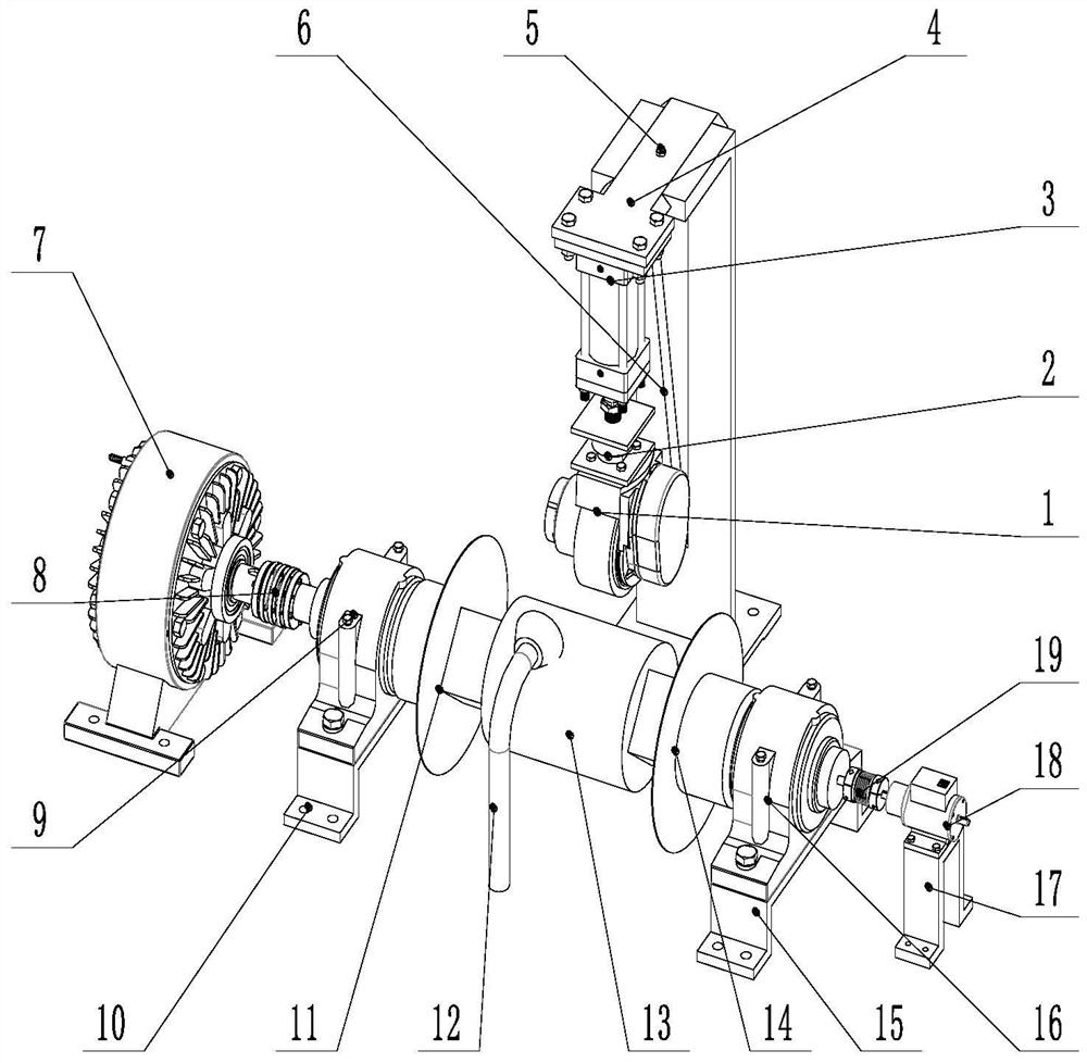
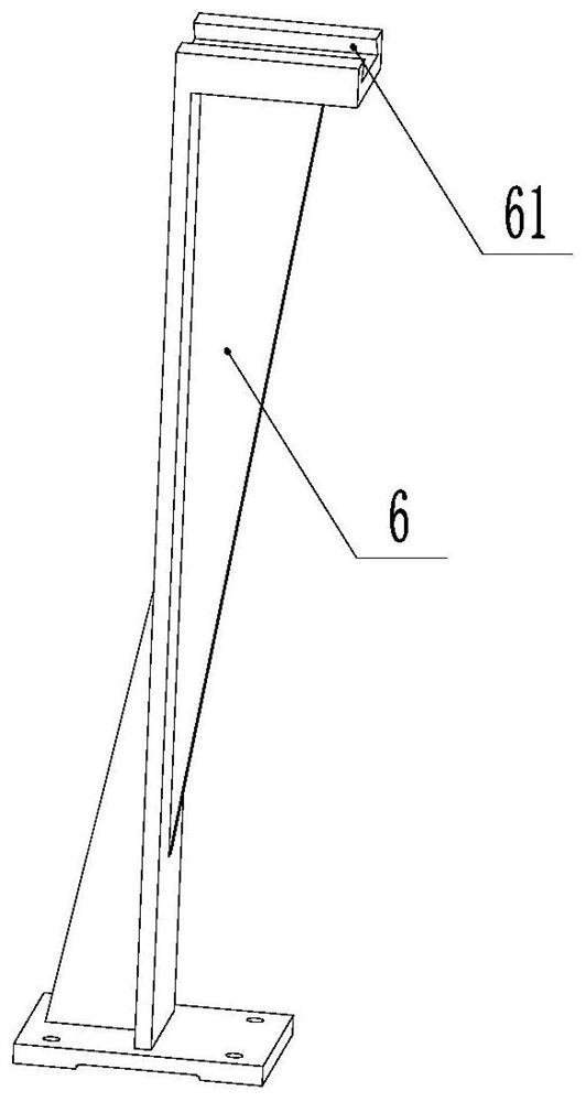
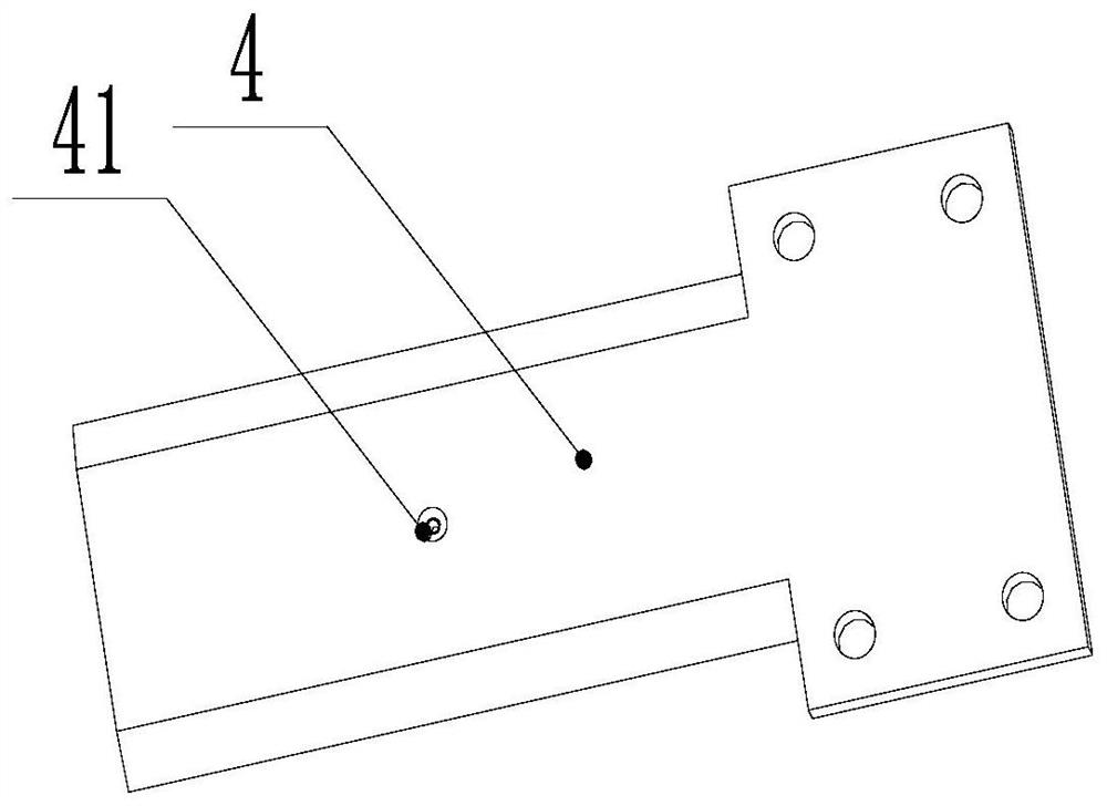
[0067] Embodiment 2 The driving wheel grip and life detection device of the present invention includes a driving wheel 1, a suspension 2, a hydraulic cylinder 3, a slide plate 4, a positioning screw 5, a first support seat 6, a magnetic powder brake 7, and a first shaft coupling Device 8, first bearing seat 9, second support seat 10, first connecting shaft 11, rain sprinkler 12, roller 13, second connecting shaft 14, third support seat 15, second bearing seat 16, fourth support seat 17. A rotational speed sensor 18 and a second coupling 19. The drive wheel 1 is connected with the hydraulic cylinder 3 through the suspension 2, the hydraulic cylinder 3 and the slide plate 4 are connected by bolts, the slide plate is embedded in the upper end chute of the first support base 6, and the axis of the drive wheel 1 is aligned with the roller 13 by moving the slide plate 4 The axis remains in the same vertical plane, after the position is determined, the set screw 5 is tightened to fix...
Embodiment 3
[0073]Embodiment 3 The difference between this embodiment and Embodiment 1 is that the brake unit is a servo motor 28, and the servo motor 28 is arranged on the side of the first support part through the motor support seat 29, and is the same as the first bearing seat. shaft, the torque output shaft of the servo motor 28 is connected to the first roller shaft through the first coupling 8; the signal output end of the magnetic powder brake is electrically connected with the signal input end of the braking unit, and is used to control the output of the braking unit. Torque, that is, the output shaft of the servo motor, the first shaft coupling 8, the first bearing seat 8, the first connecting shaft 10, the roller 11, the second connecting shaft 13, the second bearing seat 15, the second shaft coupling 16. The axes of the rotational speed sensors 18 are located on the same straight line.
PUM
 Abstract
Description
Claims
Application Information
 - R&D
- Intellectual Property
- Life Sciences
- Materials
- Tech Scout
- Unparalleled Data Quality
- Higher Quality Content
- 60% Fewer Hallucinations
Browse by: Latest US Patents, China's latest patents, Technical Efficacy Thesaurus, Application Domain, Technology Topic, Popular Technical Reports.
© 2025 PatSnap. All rights reserved.Legal|Privacy policy|Modern Slavery Act Transparency Statement|Sitemap|About US| Contact US: help@patsnap.com


