Supercharge Your Innovation With Domain-Expert AI Agents!

Heat dissipation method of infrared blood vessel in-situ display instrument

A technology for display instruments and heat dissipation methods, applied in instruments, projection devices, optics, etc., can solve the problems of short standby time, high power consumption, and difficulty in maintaining the temperature gradient of RLED, GLED and BLED bases, etc.

Inactive Publication Date: 2020-09-29
秦少平
View PDF8 Cites 0 Cited by
  • Summary
  • Abstract
  • Description
  • Claims
  • Application Information

AI Technical Summary

Problems solved by technology

[0002] The heat dissipation of components is a problem that needs to be considered in the design of the instrument. If the temperature is too high, the performance of the device will decrease, and the infrared light illumination will generate a lot of heat. If the heat is not evacuated in time, the brightness of the illumination light will be reduced; at the same time, the light in the projection module It is displayed by red LED (RLED), green LED (GLED) and blue LED (BLED) in proportion. RLED, GLED and BLED generate a lot of heat during the lighting process. If they are not evacuated in time, it is difficult to maintain RLED, GLED and BLED The temperature gradient of the base leads to the decrease of the illumination brightness of the projection module and chromatic aberration; however, the heat dissipation problem and the heat dissipation sequence are not considered in detail in the current design of the infrared blood vessel in situ display instrument; especially for the micro, small, Portable infrared blood vessel in-situ display instrument has high heat generation, high power consumption, short standby time, and heat dissipation affects instrument performance

Method used


Image

  • Heat dissipation method of infrared blood vessel in-situ display instrument
  • Heat dissipation method of infrared blood vessel in-situ display instrument
  • Heat dissipation method of infrared blood vessel in-situ display instrument

Examples


Embodiment Construction

[0015] The present invention will be further described in detail below in conjunction with the accompanying drawings and specific embodiments.

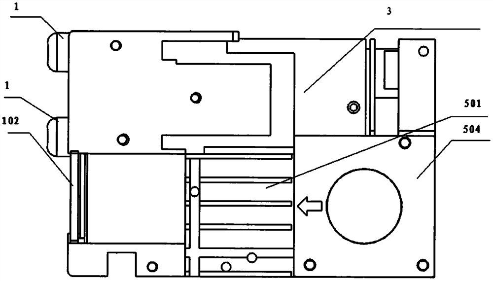
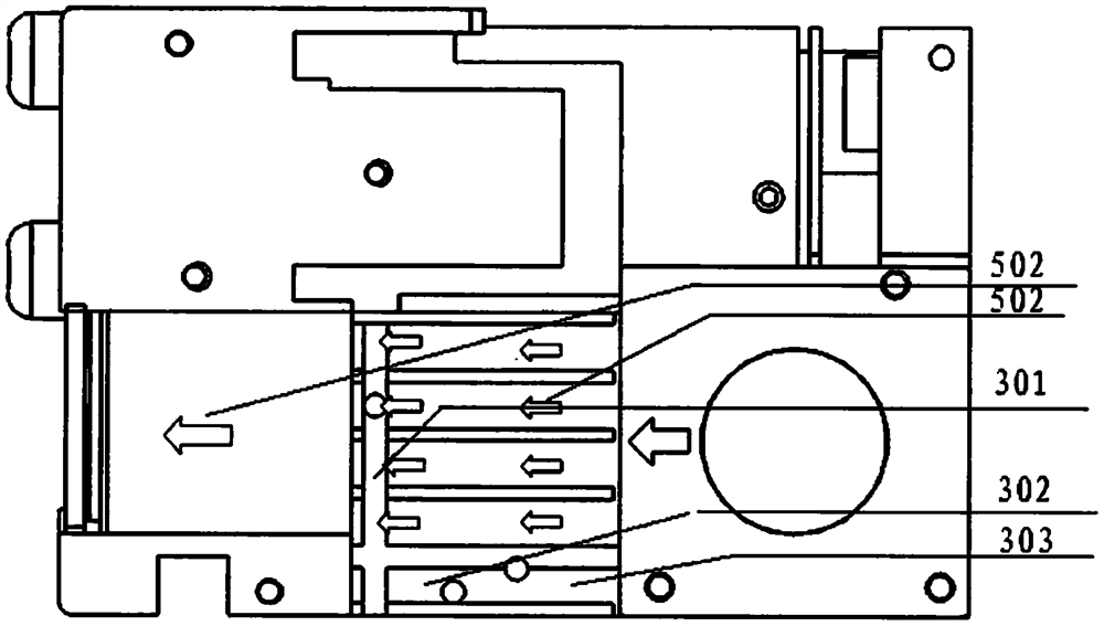
[0016] figure 1 It is a structural diagram of the whole machine of the heat dissipation method of an infrared blood vessel in-situ display instrument of the present invention, including an infrared light source module (1), an infrared camera (2), a projection module (3), a main control board (4), and a heat dissipation module ( 5); the heat dissipation module (5) adopts a fan (504) to extract cold air (502) from the outside of the instrument, and the cold air (502) is vertically inhaled from the back of the instrument, and blows on the infrared light source module (1 )superior.

[0017] The heat dissipation module (5) has multiple heat dissipation grooves (501), and the cold air takes away the heat of the projection module through the heat dissipation grooves, blows on the aluminum base (102) of the infrared light source (1), and dis...


PUM


Abstract

The utility model relates to the field of infrared light illumination and projection display, in particular to a heat dissipation system of a blood vessel in-situ display instrument. The infrared blood vessel in-situ display instrument comprises an infrared light source module (1), an infrared camera (2), a projection module (3), a main control board (4) and a heat dissipation module (5); the heatdissipation module (5) adopts a fan (504) to extract cold air (502) from the outside of the instrument, and the cold air (502) is vertically sucked from the back of the instrument, passes through a heat dissipation groove (501) and then is blown onto the infrared light source module (1) to bring heat out of the instrument; the heat dissipation module (5) is provided with a plurality of heat dissipation grooves (501), cold air passes through the heat dissipation grooves and takes away heat generated by the projection module (3) and blows on an aluminum base (102) of the infrared light source module (1) to blow away the heat generated by the infrared light source module (1), so that secondary heat dissipation of airflow is achieved. The heat dissipation module (5) enables cold air to sequentially pass through the BLED and the GLED of the projection module to cool the blue-light LED and the green-light LED, then air flow flows in the direction of the RLED to cool the red-light LED, and different color temperatures of the blue-light LED, the green-light LED and the red-light LED are guaranteed.

Description

technical field [0001] This patent relates to the field of medical auxiliary equipment, to the field of infrared lighting and projection display, and is especially used for a heat dissipation system of an infrared blood vessel in-situ display instrument. Background technique [0002] The heat dissipation of components is a problem that needs to be considered in the design of the instrument. If the temperature is too high, the performance of the device will decrease, and the infrared light illumination will generate a lot of heat. If the heat is not evacuated in time, the brightness of the illumination light will be reduced; at the same time, the light in the projection module It is displayed by red LED (RLED), green LED (GLED) and blue LED (BLED) in proportion. RLED, GLED and BLED generate a lot of heat during the lighting process. If they are not evacuated in time, it is difficult to maintain RLED, GLED and BLED The temperature gradient of the base leads to the decrease of ...

Claims


Application Information

Patent Timeline
Patent Type & Authority Applications(China)
IPC IPC(8): G03B21/16
CPCG03B21/16
Inventor 秦少平王雅娜孙长森
Owner 秦少平
Features
  • R&D
  • Intellectual Property
  • Life Sciences
  • Materials
  • Tech Scout
  • Unparalleled Data Quality
  • Higher Quality Content
  • 60% Fewer Hallucinations
Learn More