Switched reluctance motor with kinetic energy recycling capability

A switched reluctance motor and kinetic energy recovery technology, which is applied in the direction of electrical components, electromechanical devices, electric components, etc., can solve the problems of inconvenient disassembly and maintenance, large vibration amplitude at the bottom, unfavorable maintenance of the kinetic energy recovery and utilization function of switched reluctance motors, etc., to achieve Conducive to strengthening the installation and improving the effect of stability

Pending Publication Date: 2020-09-29
苏州优控动力技术有限公司
View PDF0 Cites 0 Cited by
  • Summary
  • Abstract
  • Description
  • Claims
  • Application Information

AI Technical Summary

Problems solved by technology

[0004] The purpose of the present invention is to provide a switched reluctance motor with the ability to recover and utilize kinetic energy, so as to solve the problem that the switched reluctance motors on the market proposed in the above background technology are difficult to reinforce and install the switched reluctance motor, and the vibration amplitude at the bottom is too large , affect the overall stability of the switched reluctance motor, the external disassembly and maintenance are inconvenient, the kinetic energy recovery and utilization function maintenance of the switched reluctance motor is unfavorable, and the cost of the external anti-seismic structure is too high

Method used


Image

  • Switched reluctance motor with kinetic energy recycling capability
  • Switched reluctance motor with kinetic energy recycling capability
  • Switched reluctance motor with kinetic energy recycling capability

Examples


Embodiment Construction

[0027] The following will clearly and completely describe the technical solutions in the embodiments of the present invention with reference to the accompanying drawings in the embodiments of the present invention. Obviously, the described embodiments are only some, not all, embodiments of the present invention. Based on the embodiments of the present invention, all other embodiments obtained by persons of ordinary skill in the art without making creative efforts belong to the protection scope of the present invention.

[0028] In the description of the present invention, unless otherwise stated, the meaning of "plurality" is two or more; the terms "upper", "lower", "left", "right", "inner", "outer" , "front end", "rear end", "head", "tail", etc. indicate the orientation or positional relationship based on the orientation or positional relationship shown in the drawings, and are only for the convenience of describing the present invention and simplifying the description, rather...


PUM


Abstract

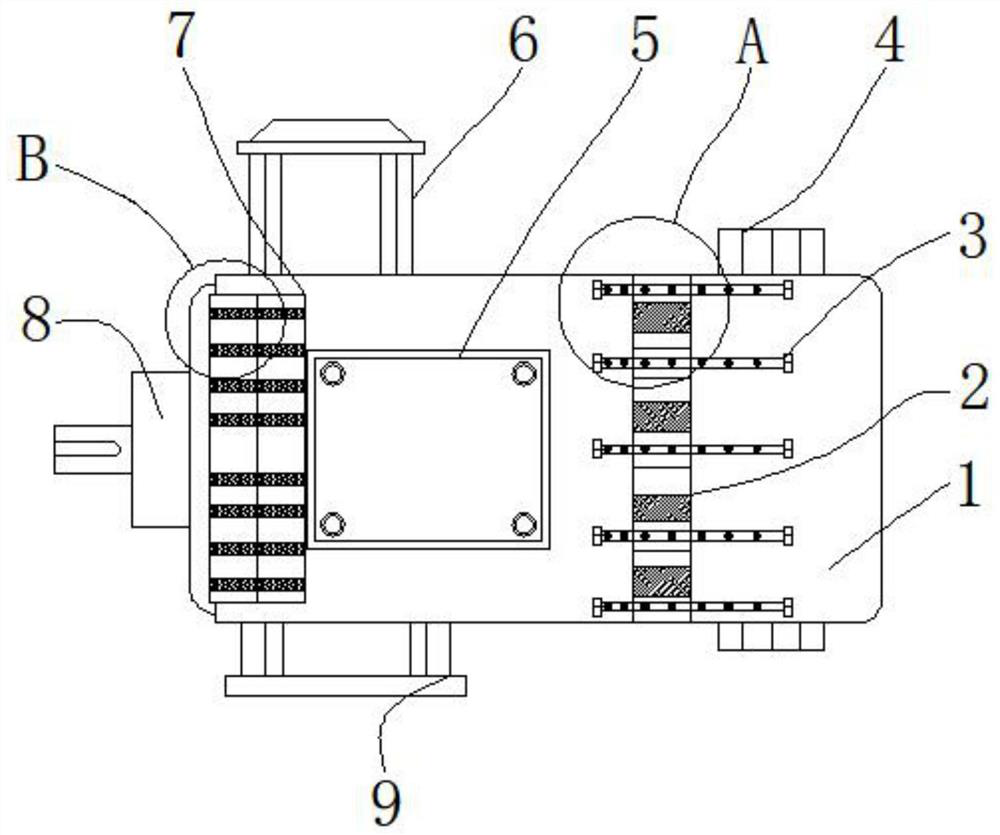
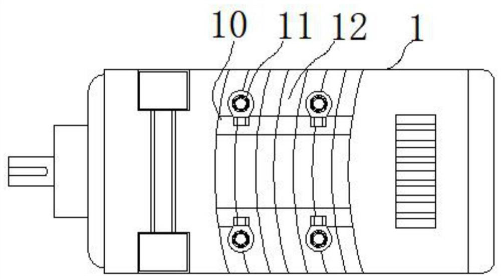
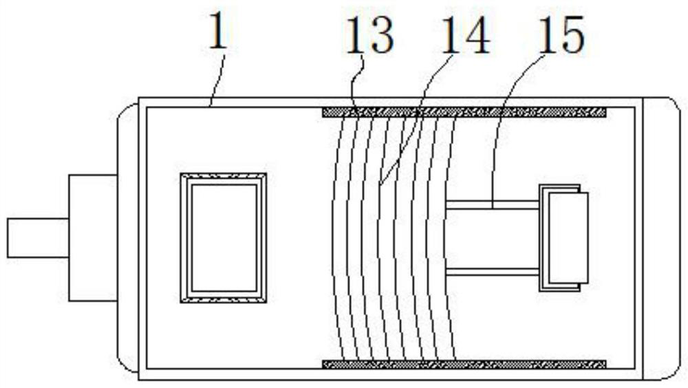
The invention relates to a switched reluctance motor with kinetic energy recycling capability. The motor comprises a motor shell, an adjusting bolt and an inner cover, a limiting plate is arranged inthe motor shell; a protection plate is arranged in the middle of the limiting plate; an equipment plate is arranged on one side of the limiting plate; a push plate is arranged on one side of the top end of the motor shell; a connecting plate is arranged on the other side of the top end of the motor shell; a vertical structure is formed between the motor shell and the connecting plate; an externalprotective sleeve plate is arranged on one side of the equipment plate; a main shaft frame is arranged on one side of the outer part of the motor shell. The motor has the advantages that: a user can manually push a top cover to slide between sliding grooves, the top cover is effectively protected in the middle of the top end of the motor shell in a sliding mode, the user can manually push a push frame to drive the top cover to be protected in the middle of the top end of the motor shell in a sliding mode, the external disassembly and maintenance are facilitated, and the kinetic energy recycling function of the switched reluctance motor can be maintained.

Description

technical field [0001] The invention relates to the technical field of switched reluctance motors, in particular to a switched reluctance motor with kinetic energy recycling capability. Background technique [0002] Switched reluctance motor is a new type of speed regulating motor. The speed regulating system has the advantages of both DC and AC speed regulating systems. It is the latest generation of stepless speed regulating system following frequency conversion speed regulating system and brushless DC motor speed regulating system. It has a simple and firm structure, a wide speed range, excellent speed regulation performance, high efficiency in the entire speed range, and high system reliability. However, there are installation defects when the switched reluctance motor is used for kinetic energy recovery. [0003] For switched reluctance motors on the market, it is difficult to reinforce and install switched reluctance motors. The vibration amplitude at the bottom is too...

Claims


Application Information

Patent Timeline
Patent Type & Authority Applications(China)
IPC IPC(8): H02K5/00H02K5/04H02K5/24
CPCH02K5/00H02K5/04H02K5/24
Inventor 张振国杨小猛
Owner 苏州优控动力技术有限公司
Why Eureka
Try Eureka