Thoracentesis positioning device for respiratory physicians
A positioning device and respiratory internal medicine technology, applied in the direction of puncture needles, trocars, etc., can solve the problems of hand shaking, puncture, and unsatisfactory use, and achieve the effect of easy disassembly and easy use
- Summary
- Abstract
- Description
- Claims
- Application Information
AI Technical Summary
Problems solved by technology
Method used
Image
Examples
Embodiment 1
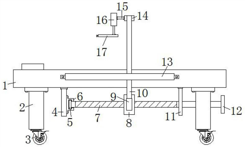
[0026] Embodiment one, with reference to figure 1 and Figure 4 A thoracentesis positioning device for respiratory medicine, comprising a bed board 1, the bottom of the bed board 1 is located at four corners and is fixed with a column 2 by bolts, the bottoms of the four columns 2 are all equipped with universal wheels 3 by bolts, the bed board 1 The bottom of the first fixed block 4 and the second fixed block 11 are fixed by bolts, the second fixed block 11 is embedded with a first screw rod 7, and the end of the first screw rod 7 close to the first fixed block 4 is provided with a fixed sleeve 6, and the fixed sleeve 6 and the first fixed block 4 are fixed by bolts, the outer wall of the first screw rod 7 is provided with a moving block 8, one side of the moving block 8 is fixed with a connecting rod 9 by bolts, and one side of the bed board 1 A positioning bar 13 is fixed by bolts, and a long slot 1301 is provided in the positioning bar 13, and a vertical bar 10 is slidably...
Embodiment 2
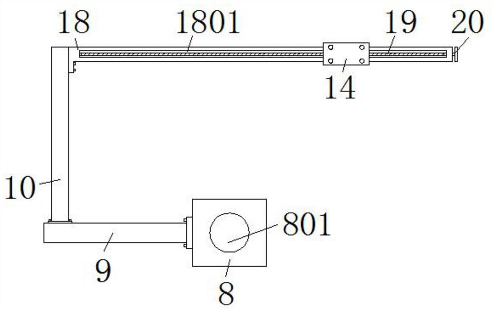
[0027] Embodiment two, refer to figure 1 , figure 2 and Figure 5 : the front of the cross bar 18 is provided with a chute 1801, a slide block 27 is slidably arranged in the chute 1801, the slide block 27 is welded with the inner wall of the slide sleeve 14, and the slide sleeve 14 can be stably mounted on the cross bar 18 through the slide block 27 Sliding up, the slide block 27 is provided with an internally threaded hole 2701, and the internally threaded hole 2701 is internally threaded to be connected with a second screw mandrel 19, and the smooth end of the second screw mandrel 19 extends to the outside of the cross bar 18 and is welded with a handwheel 20, so that Turn the handwheel 20 so that the second screw mandrel 19 drives the slider 27 to slide in the chute 1801. When the puncture position in the width direction needs to be adjusted, the handwheel 20 can be turned so that the handwheel 20 drives the second screw mandrel 19 Turning, the second screw rod 19 will m...
Embodiment 3
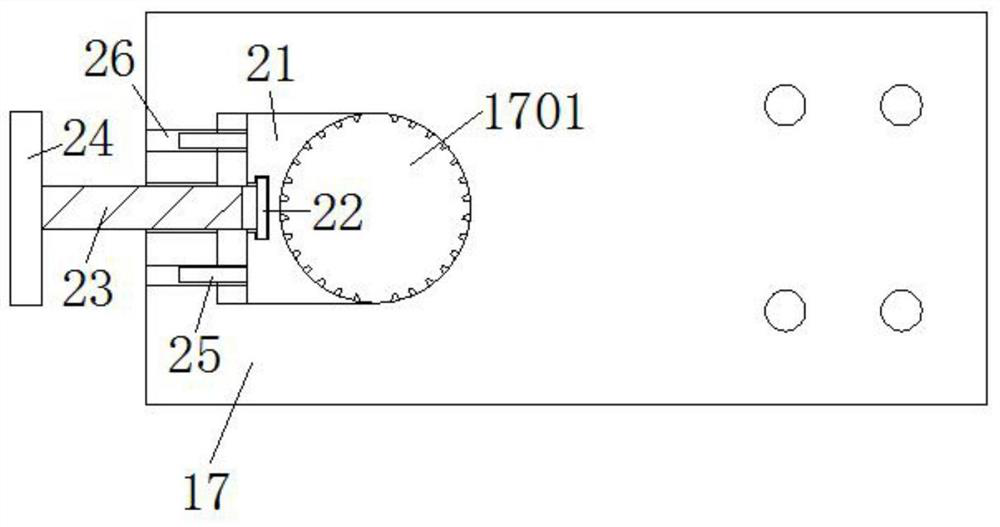
[0028] Embodiment three, refer to figure 1 and image 3: the fixed plate 17 is provided with a movable groove 1701, and a clamp block 21 is slidably arranged in the movable groove 1701, and the arc-shaped inner wall of the clamp block 21 and the corresponding side of the movable groove 1701 are bonded with rubber protrusions, and the clamp block 21 is rotated and set There is a third screw mandrel 23, the threaded section of the third screw mandrel 23 extends to the outside of the fixed plate 17 and is welded with a rotating disk 24, and the smooth end of the third screw mandrel 23 is welded with a rotating block 22, and the rotating block 22 is rotatably arranged on the clip In the block 21, turn the rotating disk 24 to realize the movement of the clamping block 21, which is convenient for fixing or taking off the puncture needle. A circular hole 26 is provided in the fixed plate 17, and a positioning rod 25 is slidably arranged in the circular hole 26, and the positioning ro...
PUM
 Abstract
Description
Claims
Application Information
 - R&D
- Intellectual Property
- Life Sciences
- Materials
- Tech Scout
- Unparalleled Data Quality
- Higher Quality Content
- 60% Fewer Hallucinations
Browse by: Latest US Patents, China's latest patents, Technical Efficacy Thesaurus, Application Domain, Technology Topic, Popular Technical Reports.
© 2025 PatSnap. All rights reserved.Legal|Privacy policy|Modern Slavery Act Transparency Statement|Sitemap|About US| Contact US: help@patsnap.com


