
Bracket positioning device

A positioning device and bracket technology, applied in the field of medical equipment, can solve problems such as long operation time and affecting the orthodontic results, and achieve the effects of reducing insufficient precision, improving bonding efficiency and bonding accuracy, and reducing orthodontic time.

Active Publication Date: 2020-10-02
THE SECOND PEOPLES HOSPITAL OF SHENZHEN
View PDF10 Cites 1 Cited by
  • Summary
  • Abstract
  • Description
  • Claims
  • Application Information

AI Technical Summary

Problems solved by technology

There are certain errors in using this method, and it needs to rely on the doctor's own experience. The operation time is long, and it has a great test for the cooperation between doctors and patients. In the later stage of correction, the brackets often need to be rebonded due to errors, which affects the Treatment results

Method used


Image

  • Bracket positioning device
  • Bracket positioning device
  • Bracket positioning device

Examples


Embodiment 1

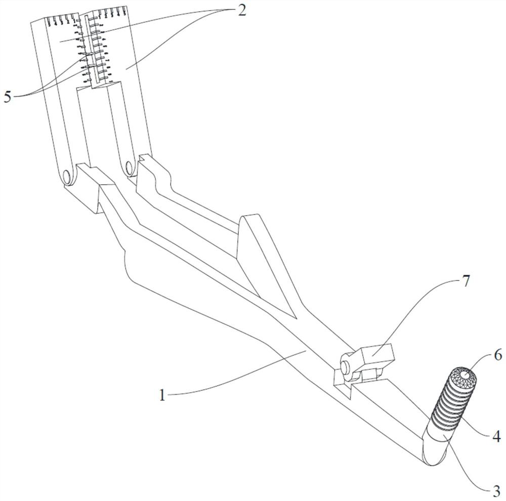
[0063] Refer below Figure 1-Figure 3 A bracket positioning device according to a specific embodiment of the present invention is described.

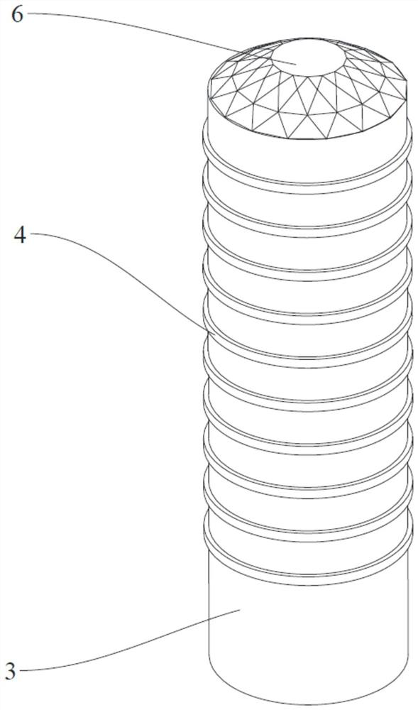
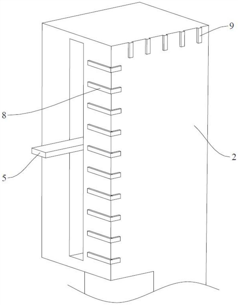
[0064] Such as Figure 1-Figure 3 As shown, the bracket positioning device of this embodiment includes a holding member 1, a probe 3, a positioning member 5, an anti-wear member 6, a detection assembly and an illuminating member 7.

[0065] The holding part 1 includes medical tweezers, and the two clamping arms on the medical tweezers are rotatably provided with clamping parts 2, and each clamping part 2 is provided with a positioning part 5. A sliding groove is provided on the clamping member 2, and the positioning member 5 is slidably arranged in the sliding groove. The clamping member 2 is provided with a vertical scale portion 8 and a horizontal scale portion 9, the length of the vertical scale portion 8 is 4mm-6mm, the length of the horizontal scale portion 9 is 1mm-2mm, and the vertical scale portion 8 includes a plurality of in...

Embodiment 2

[0072] Refer below Figure 4 A bracket positioning device according to another specific embodiment of the present invention is described.

[0073] The structure of the bracket positioning device of this embodiment is substantially the same as that of Embodiment 1. The difference between the two is the connection structure between the probe 3 and the holding member 1. Only the difference between the two is described here. This embodiment The same structure as that of Embodiment 1 will not be repeated here.

[0074] Such as Figure 4 As shown, the probe 3 of this embodiment is rotatably connected to the handle 1 .


PUM


Abstract

The invention discloses a bracket positioning device. The bracket positioning device is used for positioning a bracket on a dental surface and comprises a holding piece, a probe, a positioning piece and an anti-abrasion piece, wherein a clamping piece is arranged at one end of the holding piece and used for clamping the bracket; the probe is connected with the other end of the holding piece; a scale identification part is arranged on the probe which is used for measuring the position information of the tooth surface; the positioning piece is arranged on the clamping piece and can position thebracket on the dental surface; and the anti-abrasion piece is connected with one end, far away from the holding piece, of the probe and is used for reducing abrasion of the probe. According to the bracket positioning device, the bonding efficiency and bonding accuracy of the bracket on the tooth surface can be improved; the bonding difficulty of the bracket is reduced; meanwhile, the orthodontic duration of a patient is effectively shortened.

Description

technical field [0001] The invention relates to the technical field of medical instruments, in particular to a bracket positioning device. Background technique [0002] In the orthodontic treatment of the Department of Stomatology, the fixed orthodontic technique is often the most commonly used. This technique is to apply the orthodontic arch wire and other orthodontic accessories ligated in the bracket groove by bonding the bracket on the tooth surface. Force moves the teeth to achieve orthodontics. In the clinical operation of stomatology, the accurate positioning of the bracket on the tooth surface is one of the most important steps of bracket bonding. In the prior art, medical personnel often use a dental probe to obtain the bracket placement point first, then use ordinary medical tweezers to pick up the bracket, and glue the bracket to the previous bracket placement point through experience and visual inspection. There are certain errors in using this method, and it n...

Claims


Application Information

Patent Timeline
Patent Type & Authority Applications(China)
IPC IPC(8): A61C7/14A61C7/16
CPCA61C7/146A61C7/16
Inventor 张晓洁陈英徐迹张敏刘文兰林楚如李军心方宇翔张奕奋
Owner THE SECOND PEOPLES HOSPITAL OF SHENZHEN
Learn More