Method for producing a continuous bonding agent carpet and road finisher

a technology of bonding agent and carpet, which is applied in the direction of roads, roads, construction, etc., can solve the problems of undesirable environmental load and wrong dosing of bonding agen

Active Publication Date: 2009-12-15
JOSEPH VOEGELE AG
View PDF7 Cites 15 Cited by
  • Summary
  • Abstract
  • Description
  • Claims
  • Application Information

AI Technical Summary

Benefits of technology

[0007]It is an object of the invention to provide a method and a road finisher designed for carrying out the method which allow to produce a substantially ideal rectangular sprayed carpet having continuous straight and lineally front and rear boundaries despite given offsets between the spraying facilities and without cumbersome manual work, without wasting bonding agent, and without an unnecessary contamination of the planum.
[0008]Since according to the method each spraying facility first is activated depending on the travelling movement when it has a predetermined distance to or is reaching the reference line set beforehand, the front boundary as well as the rear boundary of the sprayed carpet will be straight and lineally and parallel to the reference line. In this way the front and rear carpet boundaries will substantially coincide with the front and rear boundary of the laid down layer, without wasting bonding agent or without unnecessary contamination of the planum. Of course, in practice, a certain overlap is made, i.e., the front and rear boundaries of the sprayed carpet will be situated a little in front of the front boundary and a little behind the rear boundary of the laid down layer, in order to prevent regions of the laid down cover layer from not bonding properly. Any manual work is eliminated which in most cases meant a wrong dosing of the bonding agent and an undesirable environmental load.
[0016]At an end of a spraying process, preferably, after the sequential deactivation of the spraying facility, either automatically or guided by an operator, a pressurised air cleaning cycle and emptying cycle at least of the spraying facilities is carried out. In this fashion clogging of the spraying facilities during an unexpectedly longer break is prevented.
[0019]An expedient embodiment of a road finisher is characterised in that in the spraying system a first spraying facility is arranged at an angle of 90 degrees with respect to the longitudinal axis of the road finisher in the front region of the road finisher. The first spraying facility serves to spray the intermediate space between the travelling lanes of an undercarriage. Two further spraying facilities are arranged at an angle of 90 degrees with respect to the longitudinal axis of the road finisher in the rear region behind the travelling lanes in order to spray the uncovered travelling lanes which have been left free by the first spraying facility. Furthermore, two spraying facilities are provided outside the travelling lanes between the front region and the rear region of the road finisher. These spraying facilities either can be displaced laterally to the longitudinal axis of the road finisher or can be pivoted in relation to the longitudinal axis of the road finisher. Each of these spraying facilities comprises several spraying nozzles which are distributed in the longitudinal direction of the respective spraying facility. The spraying nozzles can be actuated one by one, sequentially, in groups, or commonly, and in some cases cyclically. The above-mentioned distribution of the spraying facility has the advantage of allowing to use regions for the spraying facilities at the road finishers which regions offer good access. This means that only very small spraying facilities have to be arranged in the working region with obstructed access between the rear region of the chassis and the lateral distribution device in front of the paving screed. However, by using all these spraying facilities a sprayed carpet of arbitrary width can be provided, which despite the given offsets between the spraying facilities has straight and linear front and rear boundaries of the sprayed carpet lateral to the travelling direction.

Problems solved by technology

Any manual work is eliminated which in most cases meant a wrong dosing of the bonding agent and an undesirable environmental load.

Method used


Image

  • Method for producing a continuous bonding agent carpet and road finisher
  • Method for producing a continuous bonding agent carpet and road finisher
  • Method for producing a continuous bonding agent carpet and road finisher

Examples


Embodiment Construction

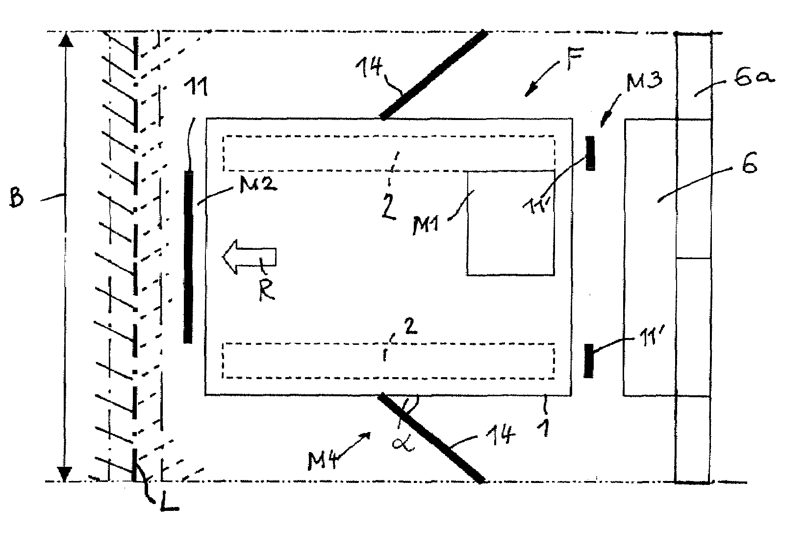
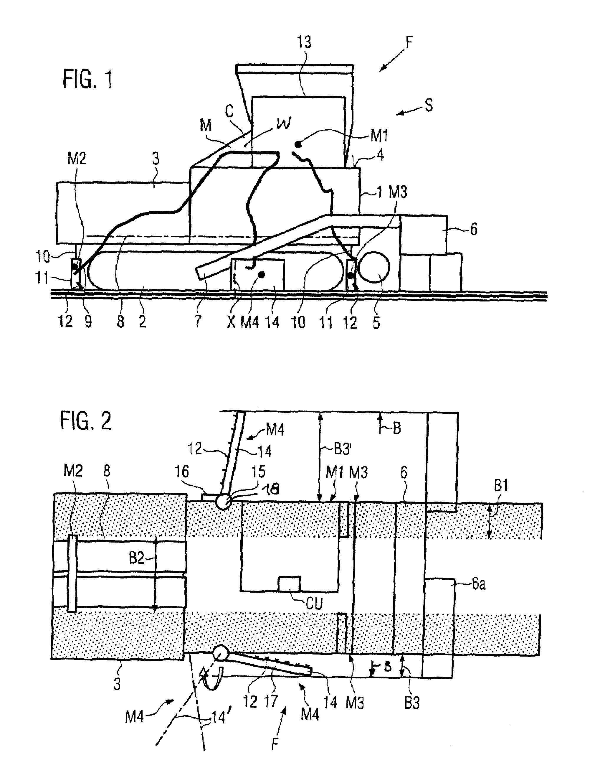
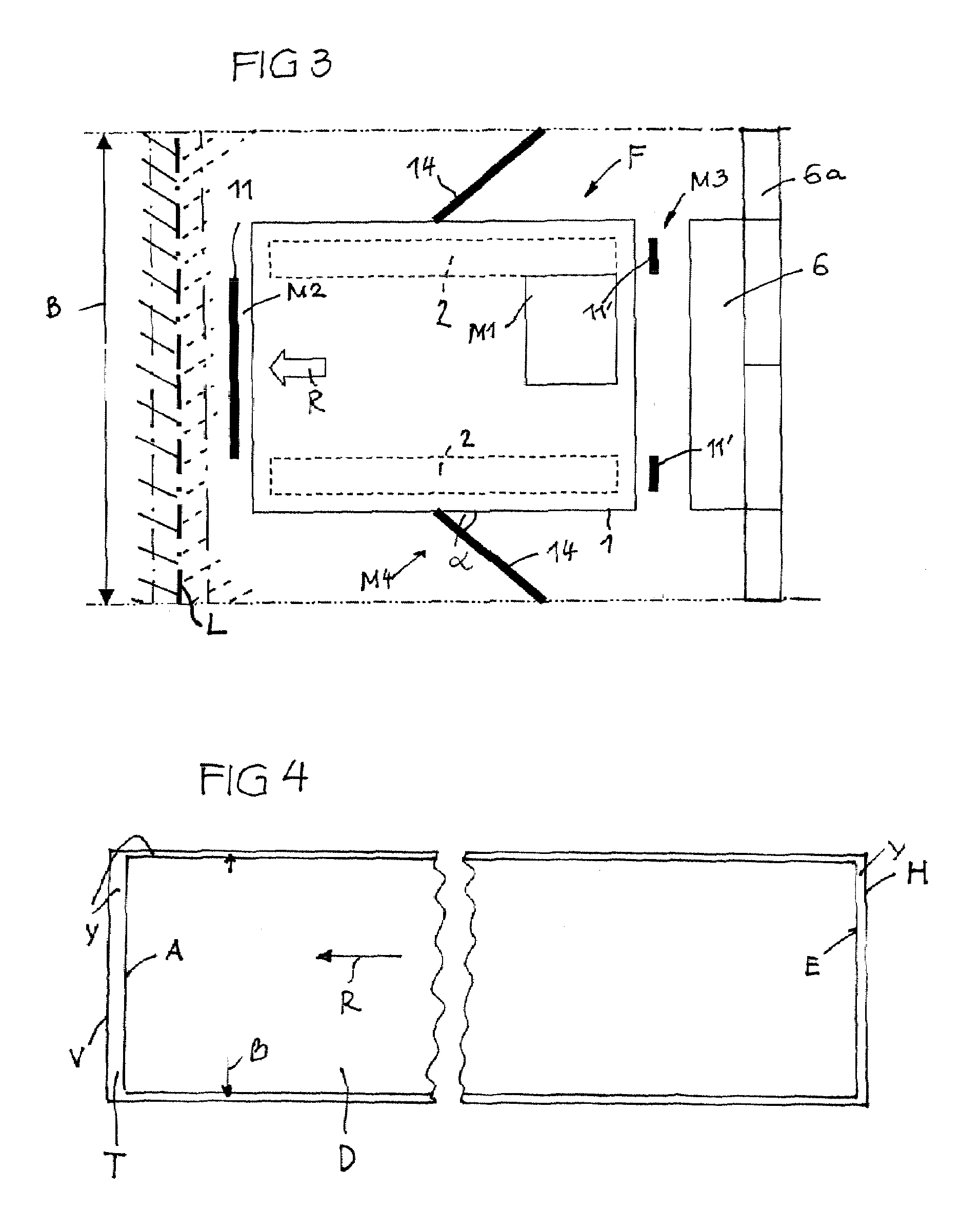
[0028]A road finisher F, in particular, a standardised road finisher, e.g. for smaller working widths, has a chassis 1 at which at the lower side an undercarriage 2 is provided (either, as shown, a caterpillar track undercarriage, or, as not shown, a wheeled undercarriage). A material hopper 3 is arranged at the front end of the chassis 1. A conveying device 8 (e.g. a slat conveyor or two adjacent slat conveyors) extends from the lower side of the material hopper 3 through the chassis 1 to the rear end of the chassis 1. A primary drive source M and an electronic control device C are arranged on the chassis 1 at an operator platform 4. Behind the rear end of the chassis 1 a lateral distribution device 5 is mounted, e.g. a distributing auger, behind which a paving screed 6 is situated which is linked by bars 7 to the chassis 1 and is towed by the road finisher F on a planum P.

[0029]It is to be noted that the paving screed 6 is a so-called extension screed (as shown in FIG. 2), compris...


PUM


Abstract

A road finisher F for producing a continuous sprayed carpet T of a bonding agent on a planum has a spraying system S on a vehicle having at least two spraying facilities 11, 11′, 14, 14′ which are located offset to each other in the and laterally to the traveling motion direction R and a control device which operates the spraying facilities using a method such that during a traveling motion of the vehicle a sprayed carpet T is produced with front and rear boundaries V, H which are continuous over the width of the sprayed carpet and which are parallel to a respective reference line L which is placed on the planum in front of the spraying facility which is the frontmost in traveling motion direction. The sprayed carpet T is produced such that each spraying facility 11, 11′, 14, 14′ first is activated or deactivated depending on the traveling motion with a predetermined distance from the or when reaching the respective reference line L.

Description

CROSS REFERENCE TO PRIOR APPLICATION[0001]This application claims priority from European Patent Application No. 06024536.2, filed Nov. 27, 2006, the disclosure of which is incorporated herein by reference in its entirety.FIELD OF THE INVENTION[0002]The invention relates to a road finisher and a method of operation, such finisher to produce a rectangular sprayed carpet of a bonding agent on a surface.BACKGROUND OF THE INVENTION[0003]The road finisher known from EP 0 484 236 A includes spraying facilities which are lateral bars distributed over the longitudinal extension of the road finisher. The spraying facilities are also offset laterally to the longitudinal axis of the road finisher, in order to e.g. produce three strip-shaped sprayed lanes which result behind the road finisher in a laterally continuous carpet. A first spraying bar is arranged in front of the undercarriage and sprays the planum between the travelling lanes of the undercarriage. Secondary spraying facilities are ar...

Claims


Application Information

Patent Timeline
Patent Type & Authority Patents(United States)
IPC IPC(8): E01C19/16
CPCE01C19/48E01C19/176
Inventor BUSCHMANN, MARTINSCHAEFER, KARL-HEINZBRAUN, ARTHURZEGOWITZ, GUENTER
Owner JOSEPH VOEGELE AG
Why Eureka
Try Eureka