Method and device of adhering polarizer onto substrate

一种偏振器、粘接的技术,应用在偏振元件、仪器、胶粘剂等方向,能够解决工作效率低、偏振器粘接、粘接变差等问题,达到工作效率高、减小空间、提高生产率的效果

Inactive Publication Date: 2004-10-27
SHARP KK
View PDF2 Cites 16 Cited by
  • Summary
  • Abstract
  • Description
  • Claims
  • Application Information

AI Technical Summary

Problems solved by technology

Poor adhesion due to air bubbles
[0030] And, for the same reason, the latter common device is also not suitable for bonding the polarizer on the large liquid crystal panel, and it also has the problem of low working efficiency.

Method used


Image

  • Method and device of adhering polarizer onto substrate
  • Method and device of adhering polarizer onto substrate
  • Method and device of adhering polarizer onto substrate

Examples


Embodiment Construction

[0066] Embodiments of the present invention will be described below with reference to the drawings.

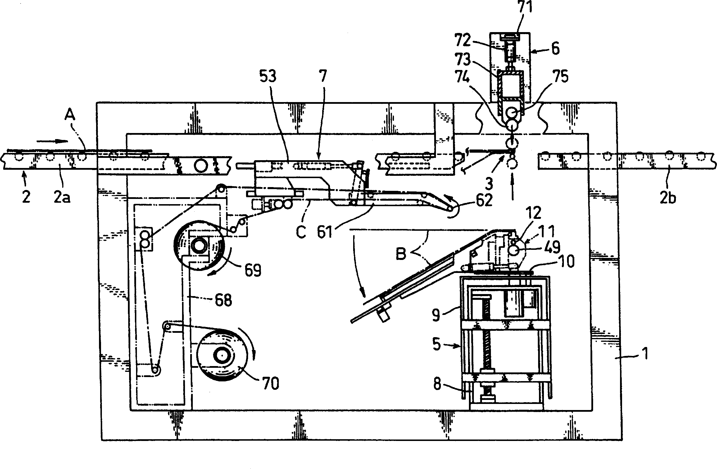
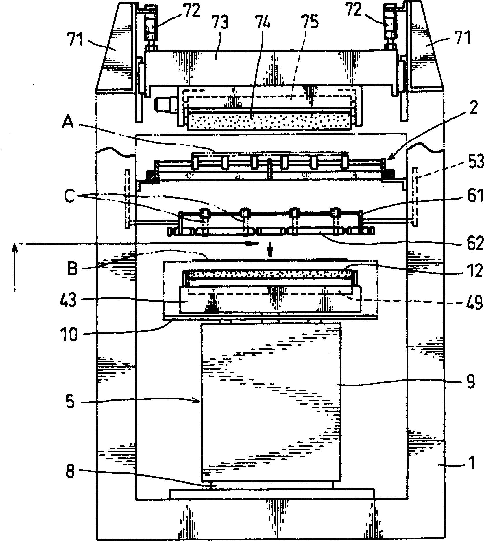
[0067] figure 1 The general structure of the device in which the polarizer is bonded to the liquid crystal panel (substrate) is shown. The transmission line 2 of the liquid crystal panel A is horizontally arranged in the upper part of the support stand body 1 . The conveying line 2 is a conveying path for a liquid crystal panel, in which a roller conveyor 2a on the input side, a roller conveyor 2b on the output side, and a polarizer B arranged at a predetermined interval between the roller conveyors 2a and 2b The bonding sites 3 are arranged in a straight line. The polarizer bonding unit 5 is arranged at a position just below the bonding position 3 . The vertically movable pressure roller mechanism 6 is arranged at a position just above the gluing station 3 . The separator peeling unit 7 is arranged at a position below the roller conveyor 2 a on the input side.

[0068] ...


PUM

PropertyMeasurementUnit
lengthaaaaaaaaaa
widthaaaaaaaaaa

Abstract

Provided is a method for sticking a polarizing plate to a liquid crystal panel particularly suitable for sticking the polarizing plate to the large size liquid crystal panel by mounting a polarizing plate sticking unit on a conveyance line of the liquid crystal panel, thus adopting a structure with no stage and saving space and making the structure compact as far as possible. A device for sticking the polarizing plate is constructed in such a way that a release sheet E of the polarizing plate B is released so as to expose an adhesive layer and subsequently the polarizing plate B is stuck to a substrate A while transferring the substrate A such as the liquid crystal panel along the conveyance line 2 in one direction from the carry-in side to the carry-out side.

Description

technical field [0001] The present invention relates to a method and apparatus for bonding a polarizer to a substrate, and more particularly to a method for bonding a polarizer to a substrate, such as a liquid crystal panel, using an adhesive layer when peeling off a separator sheet. Methods and Apparatus. Background technique [0002] Generally, a liquid crystal panel is obtained by sealing liquid crystal in a space in a liquid crystal cell formed between opposing surfaces of two glass substrates, and by bonding a polarizer to each of the two glass substrates of the liquid crystal panel. Manufactured on the outside. [0003] The polarizer has a laminated structure in which a polarizing film for polarizing light is used as a base material, one surface of the polarizer is coated with a protective film, and an adhesive applied on the other surface is protected by a separator. [0004] In the method of manufacturing a liquid crystal panel, the polarizer is adhered to an outer...

Claims


Application Information

Patent Timeline
Patent Type & Authority Applications(China)
IPC IPC(8): G02B5/30G02F1/13G02F1/1335
CPCY10T156/1744G02F1/133528Y10T156/171G02F1/13
Inventor 永田胜则冈嶋俊佑吉村和也池田幸司小西善久刀根庸浩永里智宏川岛一郎
Owner SHARP KK
Why Eureka
Try Eureka