Mini controller

A control device, control automation technology, applied in the direction of program control, computer control, electrical program control, etc., can solve problems such as data and functional reliability cannot be guaranteed

Inactive Publication Date: 2003-08-06
KLOCKNER-MOELLER GMBH
View PDF7 Cites 0 Cited by
  • Summary
  • Abstract
  • Description
  • Claims
  • Application Information

AI Technical Summary

Problems solved by technology

The data and functional reliability required for the d

Method used


Image

  • Mini controller
  • Mini controller
  • Mini controller

Examples


Embodiment Construction

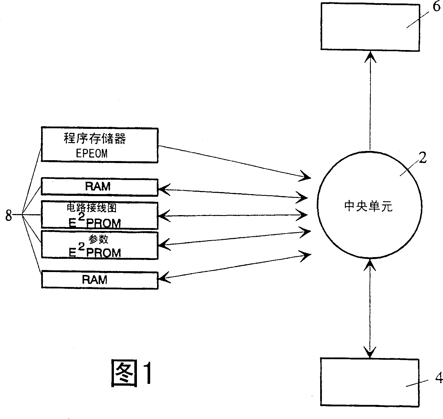
[0013] FIG. 1 shows the control device according to the invention, which has an intelligent central unit 2 , for example a microprocessor. In this case, the central unit 2 preferably takes over the entire control and communication tasks within the device. In addition, the minimum configuration as hardware includes an operating unit 4 , a display unit 6 and a memory unit 8 . All of the components listed are integrated in the control unit, eliminating the need for an additional programming unit. Operating unit 4 advantageously consists of only 4 function keys and 4 direction keys. Here, for inputting information (wiring diagram symbols or their indications or analogues and / or parameters), the 4 preferably multiple-occupied function keys "MF", "DEL", "ESC" and " OK". In order to position the cursor, four arrow keys are provided as arrow keys, which are arranged offset from each other by 90°.

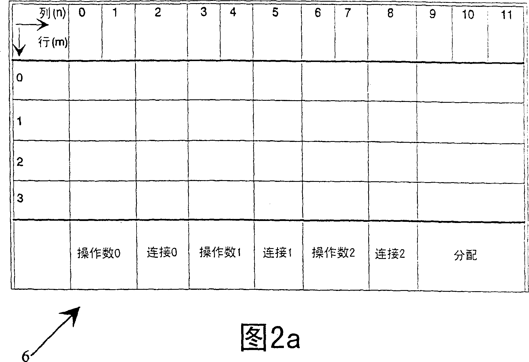
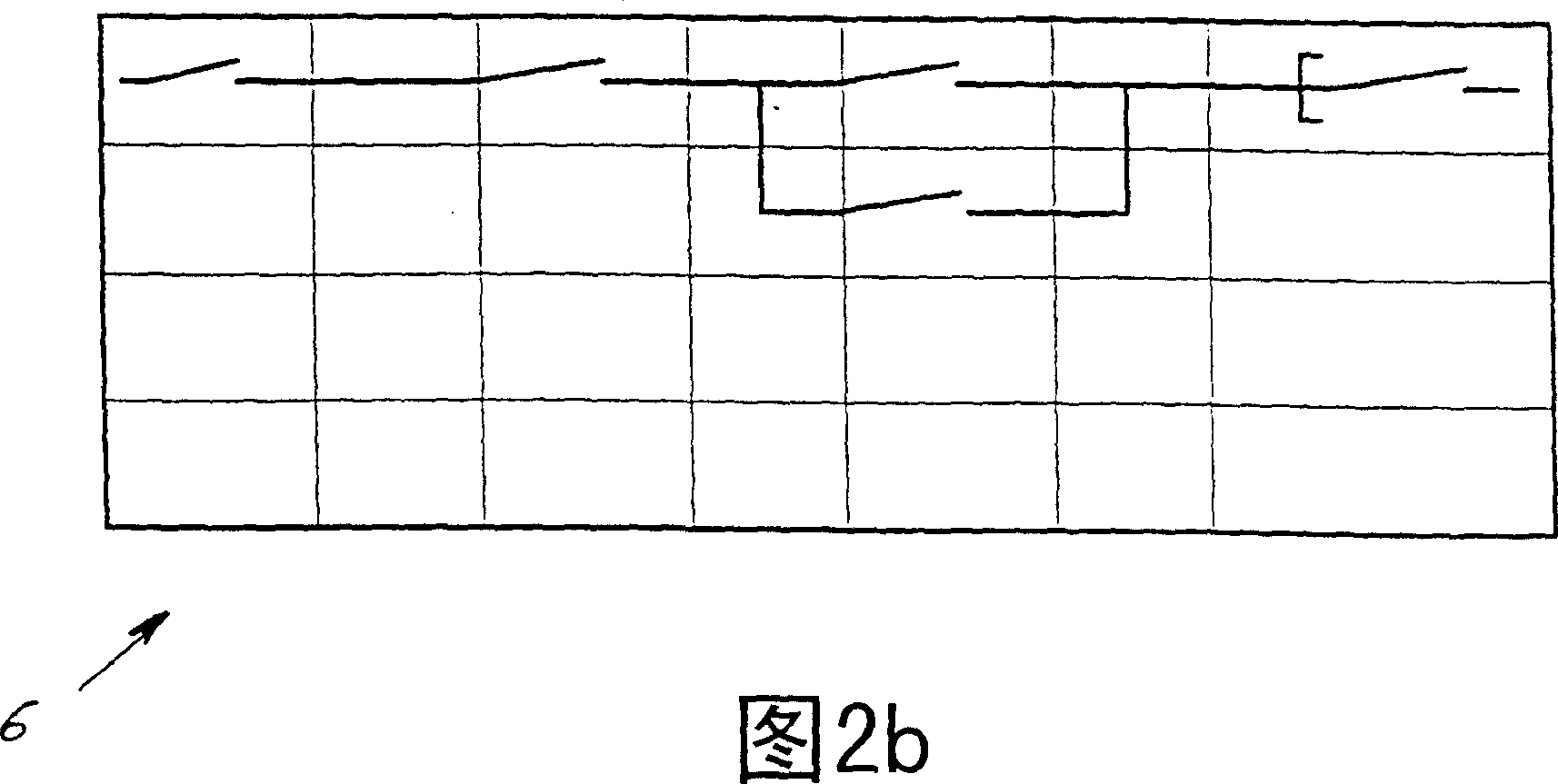
[0014] The display unit 6 consists of a character matrix with n×m (n=row, m=column)...


PUM


Abstract

A mini controller has an intelligent central unit (2), a storage unit (8), an operating unit (4) and a display unit (6). The display unit (6) is subdivided into a sign matrix with n * m sign locations, each sign location in turn being formed by an x * y pixel matrix. Each sign location is associated with a particular type of object, so that only particular types of objects can be input and processed at particular sign locations. Sign locations are provided for at least one object of the operand type, of the connection type and of the assignment type. The object types, the momentary operand states and the resulting connection states are stored in an object assignment table, so that logic-forming current paths can be created by inputting in rows and/or columns the operand, connection and assignment objects into their associated sign locations.

Description

technical field [0001] The invention relates to a small control device, in particular a programmable and / or parameterizable control device such as a logic relay, having at least the following integrated units: an intelligent central unit, a memory unit, an operating unit and an Display unit for controlling automated processes. Background technique [0002] Such devices are already known, and the logic module from Siemens (LOGO! Manual, 1996, order number 6ED1050AAOO-ODEO) is a programmable small control device of the described type for small control tasks. This device likewise has the above-mentioned integrated unit. The disadvantage here is that, due to the design of the device, programming can only be performed in a very complex manner. This programming has to be done in a way that is unfamiliar to the average user of such devices, to be precise, the usual wiring diagram (schaltplan) has to be converted into wiring lines represented by logical symbols. For this purpose,...

Claims


Application Information

Patent Timeline
IPC IPC(8): G05B19/00G05B19/05
CPCG05B19/056
Inventor 于尔根·赫格纳沃尔弗拉姆·克雷斯奥拉夫·栋
Owner KLOCKNER-MOELLER GMBH
Why Eureka
Try Eureka