A high-efficiency die-cutting machine

A die-cutting machine and high-efficiency technology, applied in metal processing and other directions, can solve the problems of affecting the accuracy of the finished product, unable to extend the length horizontally, and the diameter of the cutting die occupying a certain space, so as to avoid the effect of the horizontal diameter.

Active Publication Date: 2021-10-15
深圳市拓腾兴科技有限公司
View PDF0 Cites 0 Cited by
  • Summary
  • Abstract
  • Description
  • Claims
  • Application Information

AI Technical Summary

Problems solved by technology

[0005] In order to solve the above-mentioned technology, when the previous equipment used the fixture to clamp the processed product, in order to avoid the displacement of the workpiece during the processing, a fixed plate was installed on the outer contour of the lower end of the workpiece, resulting in , the bottom of the workpiece is extruded and cut, and the length cannot be extended laterally, and the diameter of the cutting die will occupy a certain space, so that the horizontal interception surface of the lower side of the finished workpiece will have extrusion lines, which will affect the accuracy of the finished product.

Method used


Image

  • A high-efficiency die-cutting machine
  • A high-efficiency die-cutting machine
  • A high-efficiency die-cutting machine

Examples


Embodiment 1

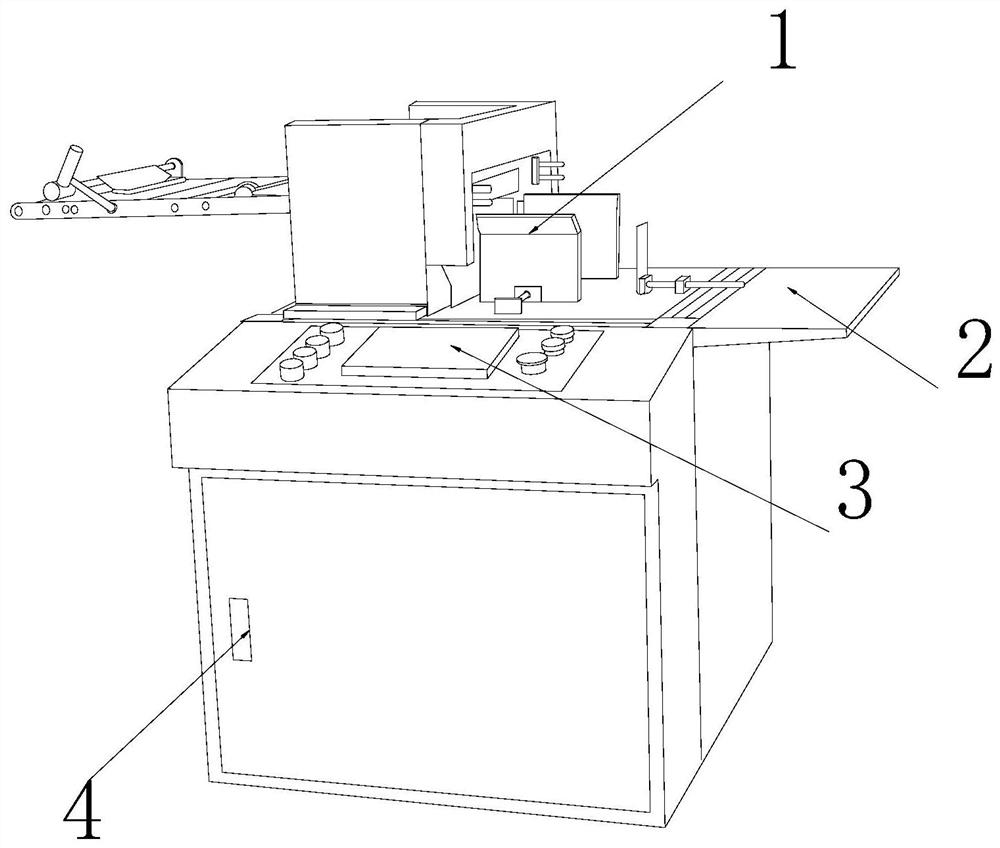
[0025] as attached figure 1 to attach Figure 5 Shown:

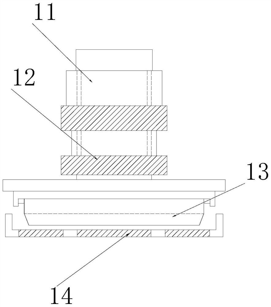
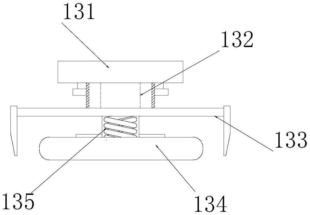
[0026] The invention provides a high-efficiency die-cutting machine, the structure of which includes a shearing device 1, a working platform 2, an operating platform 3, and an equipment box 4. The shearing device 1 is embedded and installed directly above the working platform 2. The working The platform 2 is connected to the outer surface of the upper end of the equipment box 4 by electric welding, and the operating platform 3 is inlaid and installed directly above the equipment box 4; the shearing equipment 1 includes a hydraulic rod 11, a fixed block 12, a mold mechanism 13, a fixing device 14. The lower end surface of the hydraulic rod 11 is embedded and connected with the fixed block 12, and the fixed block 12 is embedded with a mold mechanism 13. The mold mechanism 13 is located directly above the fixing device 14 and the surfaces are in contact. The fixing device 14 embeddings are installed on the upper surface o...

Embodiment 2

[0033] as attached Figure 6 to attach Figure 7As shown: the fixing device 14 includes a fixing seat 141, a rubber layer 142, a half-arc fixing block 143, and a fixing mechanism 144. The fixing seat 141 is symmetrically installed on the left and right sides of the fixing device 14, and the rubber layer 142 is inlaid Fitted and installed on the inner end surface of the half-arc fixed block 143, the half-arc fixed block 143 is connected and installed on the upper surface of the fixed seat 141 through a fixing mechanism 144, and the fixed mechanism 144 is symmetrically installed on the left and right sides of the lower end of the half-arc fixed block 143 On both sides, there are four sets of semi-arc fixing blocks 143, which can form a ring shape, and can effectively share the thrust and vibration caused by shearing during clamping.

[0034] Wherein, the fixing mechanism 144 includes a third embedding groove 4a1, an elastic cord 4f1, a second spring 4c1, and a second fixing blo...


PUM


Abstract

The invention discloses a high-efficiency die-cutting machine, which comprises a shearing device, a working platform, an operating platform, and an equipment box. The shearing equipment is embedded and installed directly above the working platform, and the working platform is connected to the upper end of the equipment box by electric welding. The outer surface and the operating platform are inlaid and installed directly above the equipment box; the shearing equipment includes a hydraulic rod, a fixed block, a mold mechanism, and a fixing device. The mechanism is located directly above the fixing device and the surfaces are in contact. During the extrusion process, the force will be evenly transmitted to the arc rubber layer through the balance plate and the support rod, and then spread flat through the expansion of the arc rubber layer to make it The workpiece is balanced and fixed to prevent the surface of the workpiece from being affected by the uneven force and unbalanced force on the precision of the workpiece.

Description

technical field [0001] The invention belongs to the field of die-cutting machines, and more specifically relates to a high-efficiency die-cutting machine. Background technique [0002] The die-cutting machine is a kind of hydraulic equipment that cooperates with the shearing model, and uses the hydraulic equipment to push the model to cut the transverse outer contour of the processed product, and then push the processed product out of the conveyor belt. [0003] Based on the discovery of the inventors above, the existing methods mainly have the following deficiencies. For example, in the past, when the equipment used the fixture to clamp the processed product, in order to avoid the phenomenon of displacement of the processed part during the processing, the processed part The outer contour of the lower end is equipped with a fixed plate, so that when the die is used to extrude, the bottom of the workpiece cannot be extended laterally during the extrusion cutting, and the diam...

Claims


Application Information

Patent Timeline
Patent Type & Authority Patents(China)
IPC IPC(8): B26F1/38B26F1/44B26D7/02
CPCB26D7/02B26F1/38B26F1/44
Inventor 王涛
Owner 深圳市拓腾兴科技有限公司
Why Eureka
Try Eureka