Cast-in-place beam support connecting device and construction process

A connection device and construction technology technology, applied in the direction of bridges, bridge parts, bridge construction, etc., can solve the problems of large consumption of welding materials, loss of steel components, waste of time, etc.

Pending Publication Date: 2020-10-02
厦门瑞达盛钢结构有限公司
View PDF8 Cites 0 Cited by
  • Summary
  • Abstract
  • Description
  • Claims
  • Application Information

AI Technical Summary

Problems solved by technology

[0003] The cast-in-place beam bracket is connected by welding, and the welding position needs to be accurately positioned. If the welding position deviates, it needs to be removed and re-welded, which not only wastes time, but also causes the loss of steel components; and the welding speed is slow, which not only increases the installation of cast-in-place beam bracket process duration and consumes a large amount of welding material

Method used


Image

  • Cast-in-place beam support connecting device and construction process
  • Cast-in-place beam support connecting device and construction process
  • Cast-in-place beam support connecting device and construction process

Examples


Embodiment

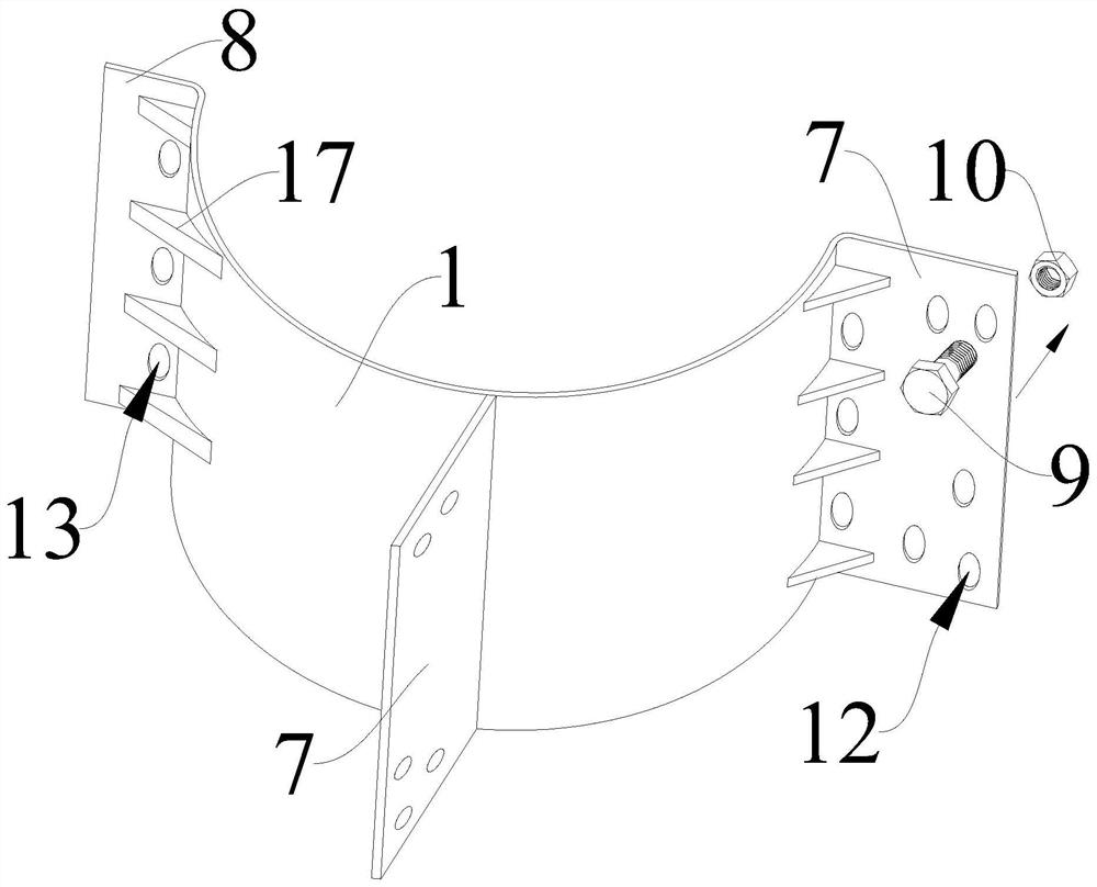
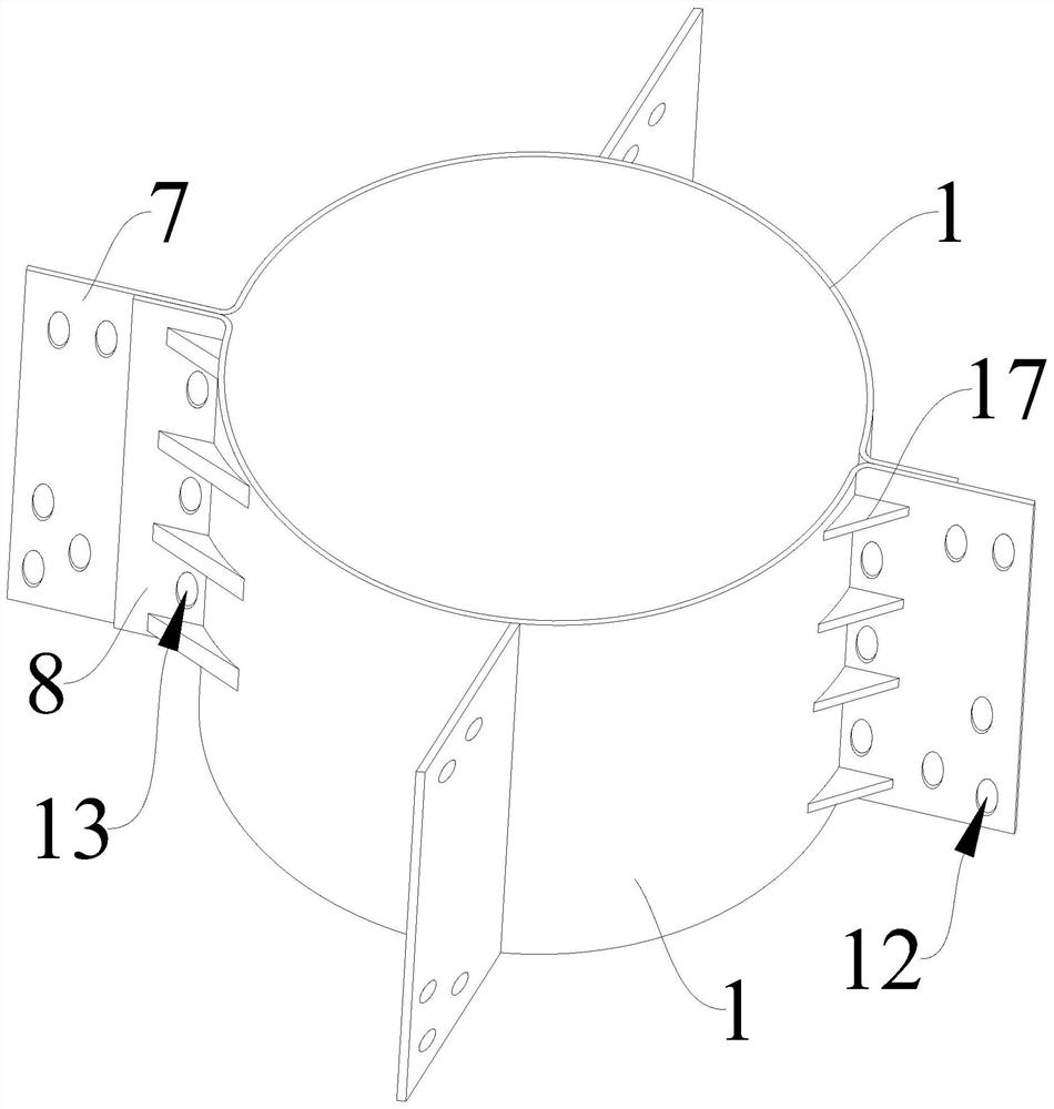
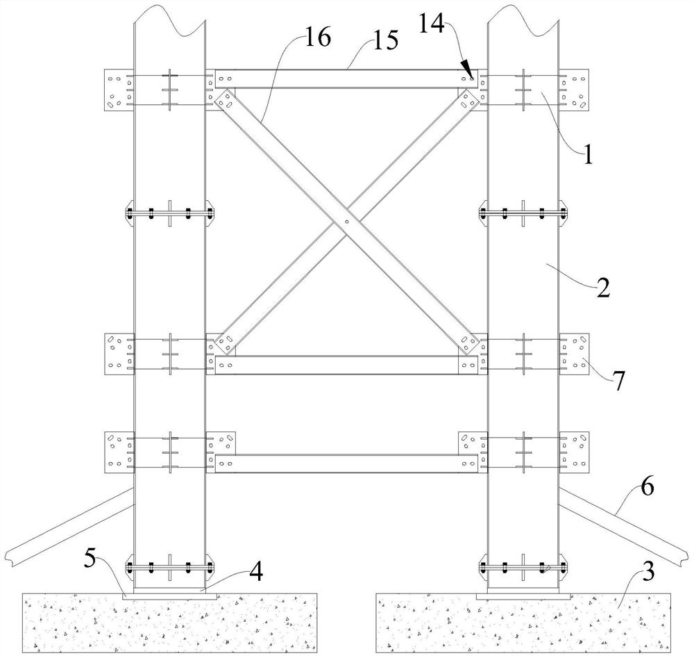
[0039] Please refer to Figure 1-Figure 5 , this embodiment provides a connection device for cast-in-place beam brackets, including a plurality of clamping components and a plurality of connecting components, any clamping component includes a clamping plate 1, and any clamping plate 1 is provided with a first trim plate 7 ; The connection assembly is detachably connected to the first panel 7 . In the present invention, by setting the clamping plate 1, the clamping plate 1 is provided with the first panel 7, and the connection assembly is detachably connected to the first panel 7, so that the two clamping plates 1 can be clamped on the column 2 as a group. The side wall is then connected to the first panel 7 through the connecting component to complete the installation of the bracket, which is convenient to install.

[0040] Such as Figure 1-Figure 5 As shown, in some embodiments of the present invention, the cross-section of the above-mentioned clamping plate 1 is semicircu...


PUM


Abstract

The invention provides a cast-in-place beam support connecting device and construction process, and relates to the technical field of building construction. The cast-in-place beam support connecting device comprises a plurality of clamping assemblies and a plurality of connecting assemblies, any clamping assembly comprises a clamping plate, and any clamping plate is provided with a first batten plate; the connecting assembly is detachably connected with the first batten plate. Therefore, the connecting device can be conveniently installed on the stand column of the support, and operation is convenient. The cast-in-place beam support construction process comprises the steps that a plurality of stand columns are horizontally placed on the ground, and a plurality of clamping assemblies are installed along the side walls of the stand columns; a foundation is poured on the ground, and the stand columns provided with the clamping assemblies are vertically installed on the foundation; the connecting assembly is installed between every two adjacent stand columns, one end of each connecting assembly is connected with the clamping assembly of one stand column, and the other end of each connecting assembly is connected with the clamping assembly of the other stand column. By adopting the device and the process, the cast-in-place beam support is convenient to install, the erecting time ofthe support is shortened, and the construction progress is accelerated.

Description

technical field [0001] The invention relates to the technical field of building construction, in particular to a cast-in-place beam support connecting device and a construction process. Background technique [0002] In the construction of cast-in-place beam supports for highways, railways, municipal projects, etc., the various components of the cast-in-place beam supports are mostly connected by welding, especially for the construction of cast-in-place beam supports for bridges. When making construction preparations, considering the factors of construction time and material turnover cycle, the planned output value is all pressed on the bridge span structure, so the duration of the installation process of each bracket needs to be shortened as much as possible. [0003] The cast-in-place beam bracket is connected by welding, and the welding position needs to be accurately positioned. If the welding position deviates, it needs to be removed and re-welded, which not only wastes ...

Claims


Application Information

Patent Timeline
IPC IPC(8): E01D21/00E01D19/00
CPCE01D19/00E01D21/00
Inventor 曹吉树
Owner 厦门瑞达盛钢结构有限公司
Why Eureka
Try Eureka