Self-priming centrifugal pumps for gas-liquid mixtures

A self-priming centrifugal pump and gas-liquid mixing technology, which is applied in the field of centrifugal pumps, can solve problems such as the centrifugal pump head flow range is not wide enough, the centrifugal pump has no self-priming ability, and cannot meet the needs of use, so as to facilitate later maintenance and management, The effect of reducing sundries entering the pump body and facilitating disassembly, cleaning and replacement

Active Publication Date: 2022-02-01
河南工学院
View PDF6 Cites 0 Cited by
  • Summary
  • Abstract
  • Description
  • Claims
  • Application Information

AI Technical Summary

Problems solved by technology

[0007] The purpose of the present invention is to provide a self-priming centrifugal pump that can handle gas-liquid mixed media, to solve the problem that the existing centrifugal pumps proposed in the background technology generally do not have self-priming ability. It is easy to fail to work normally, and at the same time, the range of head and flow rate of the existing centrifugal pump is not wide enough to meet the needs of specific environments.

Method used


Image

  • Self-priming centrifugal pumps for gas-liquid mixtures
  • Self-priming centrifugal pumps for gas-liquid mixtures
  • Self-priming centrifugal pumps for gas-liquid mixtures

Examples


Embodiment 1

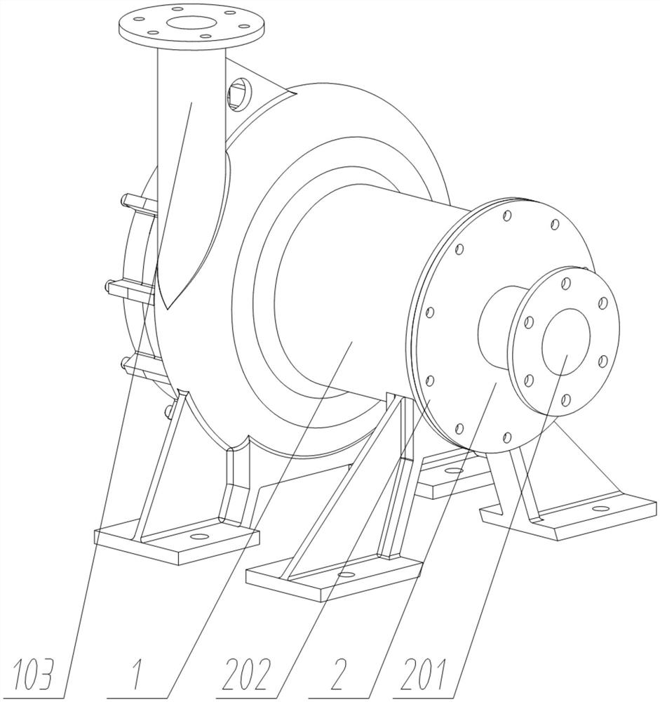
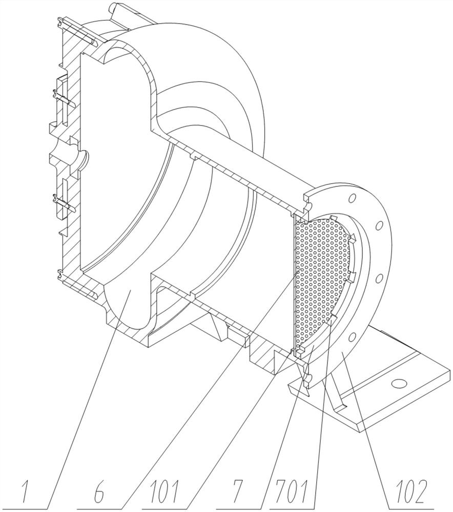
[0032] see Figure 1 to Figure 9 , the present invention provides a self-priming centrifugal pump capable of handling gas-liquid mixed media, including an outer casing 1; a group of water inlet casings 2 are fastened to the right side of the outer casing 1, and the outer casing 1 also includes an outlet Water outlet 103 , a group of water outlets 103 is provided on the top of the outer casing 1 . The water inlet housing 2 also includes a water inlet 201 , and a group of water inlets 201 is provided on the right side of the water inlet housing 2 . In use, water enters through the water inlet 201 and exits through the water outlet 103 . The outer casing 1 also includes an outer casing water inlet connection flange 102, a group of outer casing water inlet connection flanges 102 are arranged on the right end surface of the outer casing 1, and the water inlet casing 2 also includes a water inlet casing connection flange 202, The left end face of the water inlet shell 2 is fixedly...

Embodiment 2

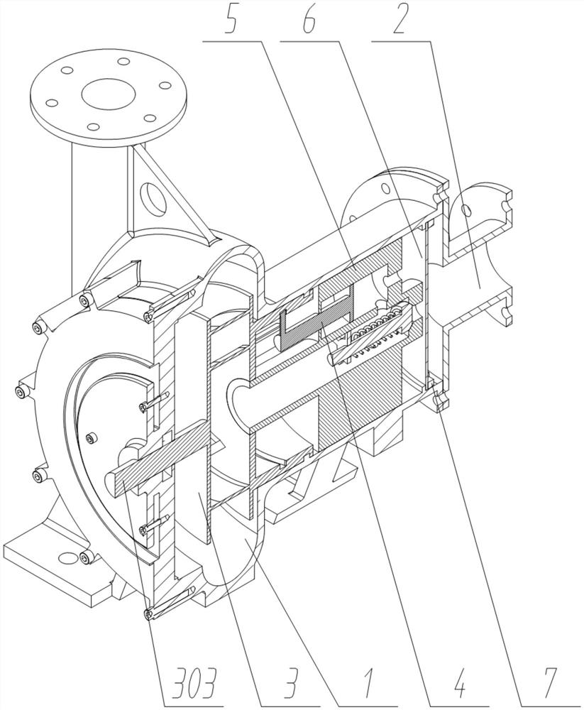
[0034] In a preferred embodiment, the impeller body 3 also includes blades 304, six sets of blades 304 are arranged inside the impeller body 3, the blades 304 are involute centrifugal blades, and the rotation of the blades 304 produces centrifugal action to dissipate the water in use. Push outward.

[0035]In a preferred embodiment, the impeller body 3 also includes an impeller guide groove 302, and a group of annular impeller guide grooves 302 are arranged on the right side of the impeller body 3, and the impeller body 3 is rotationally connected with the outer casing 1 through the impeller guide groove 302 , the outer housing 1 is guided through the impeller guide groove 302 in use.

Embodiment 3

[0037] In a preferred embodiment, the piston rod 4 also includes a piston guide groove 402, two sets of piston guide grooves 402 are arranged on the outside of the piston rod 4, and the piston rod 4 is slidingly connected with the piston cylinder body 5 through the piston guide groove 402. The piston rod 4 is guided through the piston guide groove 402 .

[0038] In a preferred embodiment, the piston cylinder 5 also includes a piston water inlet 502 and a piston water outlet 503, a group of piston water inlets 502 are arranged on the right side of the piston chamber 501, and a group of piston water outlets 503 are arranged inside the piston chamber 501 , the piston water outlet 503 opens toward the cavity in the middle of the piston cylinder 5, and a group of one-way valves are respectively arranged inside the piston water inlet 502 and the piston water outlet 503, and the one-way valve in the piston water inlet 502 opens to the piston cavity 501, and the piston The one-way val...


PUM


Abstract

The invention discloses a self-priming centrifugal pump capable of handling gas-liquid mixed media, which includes an outer casing; a group of water inlet casings are fastened to the right side of the outer casing, and a group of water outlets are arranged on the top of the outer casing for the water inlet. The right side of the water shell is provided with a group of water inlets; the right end of the outer shell is provided with a set of outer shell water inlet connecting flanges, and the left end of the water inlet shell is fixedly connected with a set of water inlet shell connecting flanges; the left end of the outer shell There is a group of impeller bodies rotatingly connected to the side; the left end surface of the impeller body is coaxially fixedly connected with a group of impeller drive shafts; the inner part on the right side of the outer shell is fixedly connected with a group of piston cylinders; the inner circumference of the piston cylinders is arranged in a sliding manner and connected with Five sets of piston rods and piston chambers; a set of water inlet filter nets are crimped and connected inside the right side of the outer shell through the filter net pressure ring. The invention can deal with different media such as gas and liquid, has strong adaptability and self-priming ability, and can provide high head while ensuring sufficient flow.

Description

technical field [0001] The invention relates to the technical field of centrifugal pumps, in particular to a self-priming centrifugal pump capable of handling gas-liquid mixed media. Background technique [0002] A centrifugal pump refers to a pump that delivers liquid by the centrifugal force generated when the impeller rotates. The basic structure of the centrifugal pump is composed of six parts: the impeller, the pump body, the pump shaft, the bearing, the sealing ring, the stuffing box, and the centrifugal pump. Compact structure, uniform flow, stable operation, low vibration, low cost of equipment installation, maintenance and overhaul are widely loved by people. [0003] Before starting the pump, the pump casing and the suction pipe must be filled with water, and then the motor is started to drive the impeller and the water to rotate at a high speed. The water undergoes centrifugal motion and is thrown to the outer edge of the impeller, and flows through the volute pum...

Claims


Application Information

Patent Timeline
Patent Type & Authority Patents(China)
IPC IPC(8): F04B23/14F04B23/10F04D1/00F04D9/02F04D29/42F04D29/22F04D29/24F04B1/16F04B1/128F04B1/143F04B1/124F04B1/122F04B9/04F04B53/10F04B53/20F04B53/22
CPCF04B23/14F04B23/106F04D1/00F04D9/02F04D29/426F04D29/4293F04D29/2261F04D29/242F04B1/16F04B1/128F04B1/143F04B1/124F04B1/122F04B9/047F04B53/10F04B53/20F04B53/22
Inventor 郑路路马晓杰璩晶磊王蒙蒙陈芳郑立爽刘玲玲席夏青
Owner 河南工学院
Why Eureka
Try Eureka