
Clamp type testing device

A testing device and clamping technology, which is applied in the direction of measuring device, measuring device casing, measuring electricity, etc., can solve the problems of easy wrinkling of batteries, battery damage, wrinkle interference, etc., and achieve the effect of reducing test interference.

Pending Publication Date: 2020-10-02
致茂电子(苏州)有限公司
View PDF9 Cites 0 Cited by
  • Summary
  • Abstract
  • Description
  • Claims
  • Application Information

AI Technical Summary

Problems solved by technology

However, when the battery is manufactured, in order to avoid electrode oxidation or damage, a protective film will be covered on the surface of the electrode. If the protective film cannot be effectively scraped off, the test connector will not be able to directly contact the electrode of the battery, resulting in inaccurate measurement. Battery voltage and current characteristics
Generally speaking, soft-pack batteries commonly used in the industry are prone to wrinkles, and are often disturbed by wrinkles when mechanically or manually removing the protective film of the electrodes.
At this time, it will not only reduce the detection efficiency of the battery, but also easily cause damage to the battery

Method used


Image

  • Clamp type testing device
  • Clamp type testing device
  • Clamp type testing device

Examples


Embodiment Construction

[0036] The aforementioned and other technical content, features and effects of the present invention will be clearly presented in the following detailed description of a preferred embodiment with reference to the accompanying drawings. The directional terms mentioned in the following embodiments, such as: up, down, left, right, front or back, etc., are only referring to the directions of the drawings. Accordingly, the directional terms are used to illustrate and not to limit the invention.

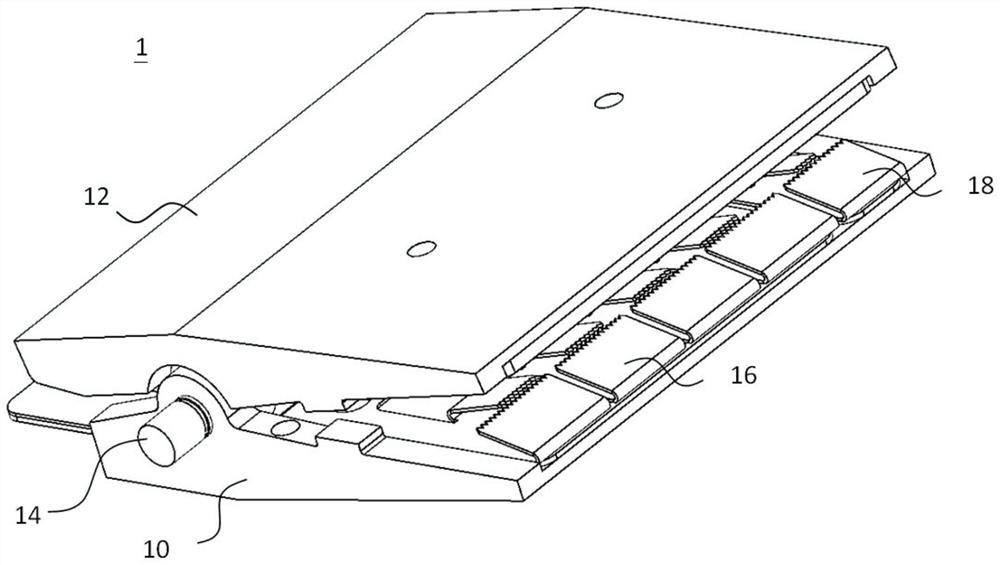
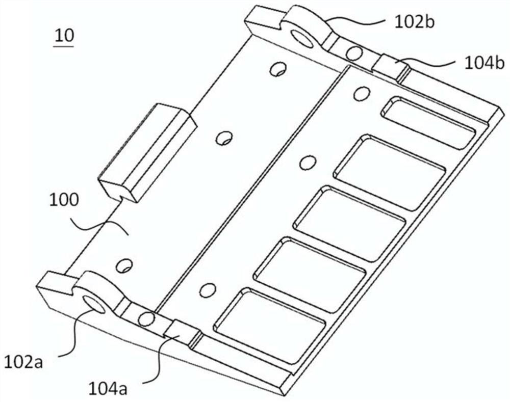
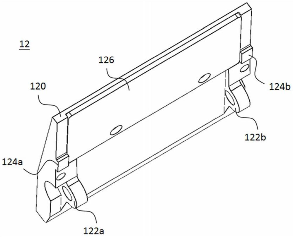
[0037] see figure 1 , figure 1 It is a three-dimensional schematic diagram illustrating a clip-type testing device according to an embodiment of the present invention. Such as figure 1 As shown, the clip-type testing device 1 includes a first clamping part 10 , a second clamping part 12 , a rotating shaft part 14 , a conductive part 16 and a measuring part 18 . The conductive member 16 is located between the first clamping component 10 and the second clamping component 12, and is close...


PUM


Abstract

The invention provides a clamp type testing device. The clamp type testing device comprises a first clamping part, a second clamping part, a rotating shaft part and a conductive part; the first clamping part is provided with a first base wall and a first pivot joint part. The second clamping part is provided with a second base wall and a second pivoting part; the rotating shaft part is detachablypivoted to the first pivoting part and the second pivoting part. The conductive part is arranged on the first clamping part and located between the first base wall and the second base wall. The conductive part comprises a body part, a plurality of first bent parts and a plurality of second bent parts. The first bent parts extend out of the body part, and a first scraping structure is arranged at the end, away from the body part, of one of the multiple first bent parts. The second bent parts extend out of the body part, a second scraping structure is arranged at the end, away from the body part, of one of the multiple second bent parts, and the second scraping structure faces the first scraping structure.

Description

technical field [0001] The invention relates to a clip-type test device, in particular to a clip-type test device with a scraping structure. Background technique [0002] With the development of electric transportation, it provides people with the option of using pure electric energy to move long distances without using fossil fuels. In order to increase the driving distance of electric vehicles, it is often necessary to install more batteries with higher capacity. However, how to ensure the stability, safety and reliability of these batteries has become an important issue, which also highlights the importance of testing battery quality. [0003] At present, when testing the battery quality, it is possible to perform charging and discharging tests for the battery, so that the voltage and current characteristics of the battery can be accurately measured, which is an important key to evaluating the quality of the battery. However, when the battery is manufactured, in order to...

Claims


Application Information

Patent Timeline
Patent Type & Authority Applications(China)
IPC IPC(8): G01R31/385G01R1/04
CPCG01R1/0416
Inventor 许旭昌许国彦
Owner 致茂电子(苏州)有限公司
Learn More