Element placement method, device and equipment of three-dimensional scene editor, and storage medium
A 3D scene and editor technology, applied in the input/output process of instruments, data processing, image data processing, etc., can solve the problems of complex operation and low efficiency of moving objects
- Summary
- Abstract
- Description
- Claims
- Application Information
AI Technical Summary
Problems solved by technology
Method used
Image
Examples
Embodiment 1
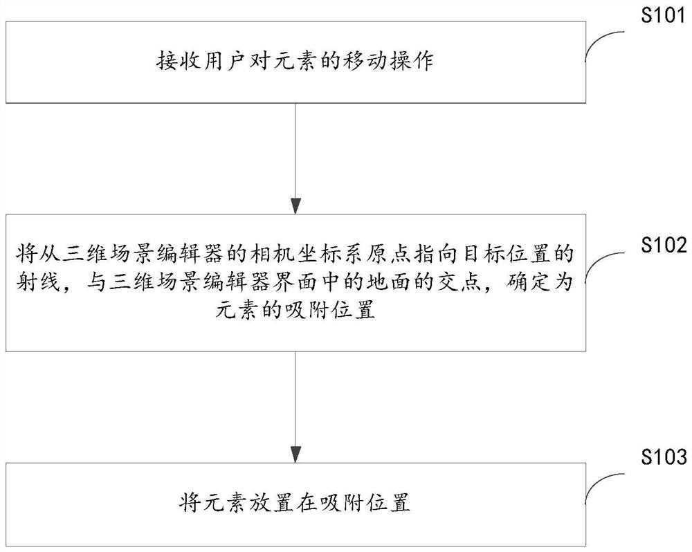
[0036] figure 1 It is a schematic flow diagram of the element placement method according to the first embodiment of the present application. The method may be executed by a software and / or hardware device. For example, the device may be an electronic device where a three-dimensional scene editor is located. Such as figure 1 As shown, the content recommendation method includes:
[0037] S101. Receive a user's movement operation on an element.
[0038] In this embodiment, the element is the basic operation unit in the 3D scene editor. For example, the 3D scene editor is an automatic driving scene editor, and the elements can be vehicles, pedestrians, roadblocks, trees, buildings, traffic lights, roads, and other objects that users can use to build an automatic driving scene. For example, the 3D scene editor is an architectural model editor, and the elements can be walls, doors and windows, stairs, furniture, and other object models that users can use to construct architectural mode...
Embodiment 2
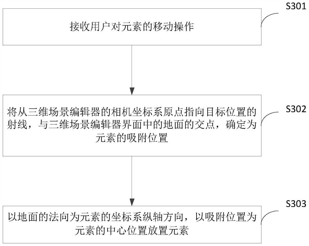
[0052] image 3 It is a schematic flowchart of the element placement method according to the second embodiment of the present application. Such as image 3 As shown, the method includes:
[0053] S301. Receive a user's movement operation on an element.
[0054] S302: The intersection of the ray from the origin of the camera coordinate system of the 3D scene editor to the target position and the ground in the interface of the 3D scene editor is determined as the adsorption position of the element.
[0055] S301-S302 in this embodiment and figure 1 S101-S102 in the illustrated embodiment are similar, and will not be repeated here.
[0056] S303. Place the element with the normal direction of the ground as the longitudinal axis direction of the element coordinate system, and the adsorption position as the center position of the element.
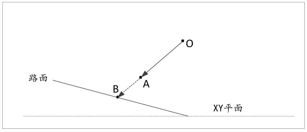
[0057] Still with figure 2 The scenario illustrated in will be placed on a sloped road surface, which is determined by steps S301-S302 figure 2 The mi...
Embodiment 3
[0064] Figure 5 It is a schematic structural diagram of an element placement device according to the third embodiment of the present application. Such as Figure 5 As shown, the element placement device 50 includes:
[0065] The receiving module 501 is configured to receive a user's movement operation on the element, and the movement operation is used to indicate the target position of the element;
[0066] The determining module 502 is used for determining the intersection of the ray from the origin of the camera coordinate system of the 3D scene editor to the target position and the ground in the interface of the 3D scene editor as the adsorption position of the element;
[0067] The placement module 503 is used to place the element in the adsorption position.
[0068] Optionally, the placement module 503 is used to:
[0069] Use the normal of the ground as the longitudinal axis of the element's coordinate system, and place the element with the adsorption position as the center of t...
PUM
 Abstract
Description
Claims
Application Information
 - R&D
- Intellectual Property
- Life Sciences
- Materials
- Tech Scout
- Unparalleled Data Quality
- Higher Quality Content
- 60% Fewer Hallucinations
Browse by: Latest US Patents, China's latest patents, Technical Efficacy Thesaurus, Application Domain, Technology Topic, Popular Technical Reports.
© 2025 PatSnap. All rights reserved.Legal|Privacy policy|Modern Slavery Act Transparency Statement|Sitemap|About US| Contact US: help@patsnap.com


