Heat dissipation device and electromechanical equipment mounting table

A heat dissipation device and electromechanical equipment technology, which is applied to the structural parts of electrical equipment, electrical components, cooling/ventilation/heating transformation, etc., which can solve the problems of inability to achieve ideal heat dissipation effect and poor heat dissipation effect

Inactive Publication Date: 2020-10-02
喻炜喆
View PDF0 Cites 0 Cited by
  • Summary
  • Abstract
  • Description
  • Claims
  • Application Information

AI Technical Summary

Problems solved by technology

[0003] The purpose of the embodiment of the present invention is to provide a heat dissipation device, aiming to solve the problem that the existing heat dissipation method of the exhaust fan directly exhausting the air has poor heat dissipation effect and cannot achieve the ideal heat dissipation effect

Method used


Image

  • Heat dissipation device and electromechanical equipment mounting table
  • Heat dissipation device and electromechanical equipment mounting table
  • Heat dissipation device and electromechanical equipment mounting table

Examples


Embodiment Construction

[0025] In order to make the object, technical solution and advantages of the present invention clearer, the present invention will be further described in detail below in conjunction with the accompanying drawings and embodiments. It should be understood that the specific embodiments described here are only used to explain the present invention, not to limit the present invention.

[0026] The specific implementation of the present invention will be described in detail below in conjunction with specific embodiments.

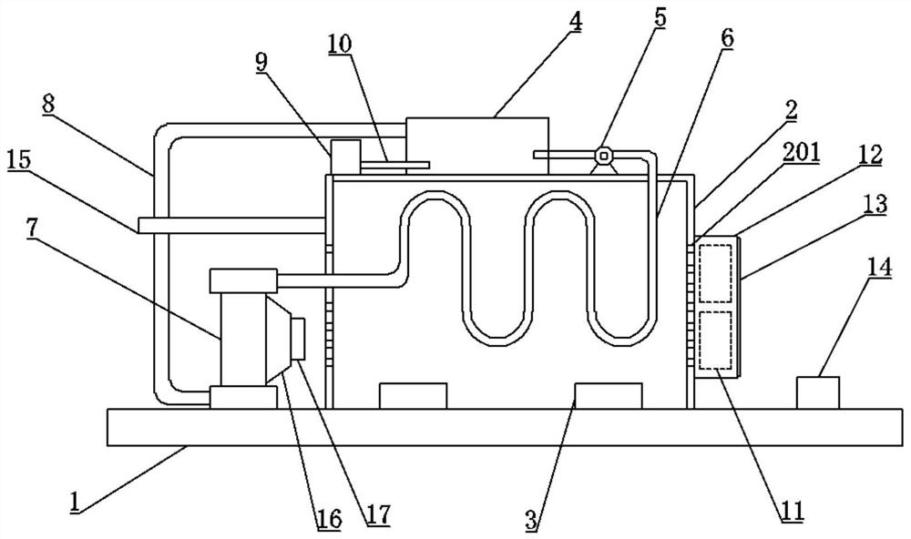
[0027] like figure 1 As shown, it is a schematic structural diagram of a heat dissipation device provided by an embodiment of the present invention, including:

[0028] The equipment installation box 2 has a mounting seat 3 for installing and fixing the electromechanical equipment on its inner bottom surface;

[0029] The fixed plate 1 is fixedly connected with the bottom surface of the equipment installation box 2, and supports the equipment installation box 2...


PUM


Abstract

The invention is suitable for the technical field of heat dissipation, and provides a heat dissipation device and an electromechanical equipment mounting table. The heat dissipation device comprises an equipment mounting box of which the internal bottom surface is fixedly connected with a mounting base; a fixed plate fixedly connected with the bottom surface of the equipment mounting box; a watertank fixed outside the equipment mounting box and communicated with the water pump. A radiator is fixedly installed on one side of the top end of the fixed plate, and a water inlet and a water outletare formed in the top end and the bottom end of the radiator respectively. A water outlet of the water pump communicates with a water inlet hole of the radiator through a water inlet pipe which is located in the equipment mounting box; a water outlet of the radiator is communicated with the water tank through a water outlet pipe; ventilation holes are formed in the two sides of the equipment mounting box, and a fan protection frame is fixedly installed on the side, away from the radiator, outside the equipment mounting box; and a first cooling fan is installed at the position, opposite to theventilation hole, of the fan protection frame, and a protection net for protecting the first cooling fan is fixedly installed outside the fan protection frame. According to the embodiment, the heat dissipation effect of the heat dissipation device can be improved.

Description

technical field [0001] The invention belongs to the technical field of heat dissipation, and in particular relates to a heat dissipation device and an electromechanical equipment mounting platform capable of active heat dissipation. Background technique [0002] With the continuous improvement of people's living standards, people have more and more demands for electromechanical equipment in their daily life. Advanced electromechanical equipment can not only greatly increase labor productivity, improve the production environment, and complete tasks that cannot be done by manpower. One of the foundations has a direct and important impact on the development of the entire national economy, as well as the improvement of science and technology and national defense capabilities. The electromechanical equipment will generate a lot of heat during the operation of the equipment. If the electromechanical equipment is heated or even hot for a long time, it will easily cause the malfunct...

Claims


Application Information

Patent Timeline
Patent Type & Authority Applications(China)
IPC IPC(8): H05K7/20
CPCH05K7/20172H05K7/20181H05K7/20263H05K7/20272
Inventor 喻炜喆
Owner 喻炜喆
Why Eureka
Try Eureka