Secondary water supply control equipment with protection function

A technology for secondary water supply and control equipment, which is applied in the direction of mechanical equipment, electrical equipment structural parts, electrical equipment shells/cabinets/drawers, etc. It can solve the problems of poor heat dissipation, waste of electric energy, damage to control equipment, etc., and achieve heat dissipation effect Good results

Pending Publication Date: 2022-03-25
重庆昕晟环保科技有限公司
View PDF0 Cites 0 Cited by
  • Summary
  • Abstract
  • Description
  • Claims
  • Application Information

AI Technical Summary

Problems solved by technology

[0004] This setting will directly expose the control equipment used for secondary water supply to the external environment. When encountering rainy and snowy weather and the sealing effect of the control equipment cabinet itself is not good, rainwater seeping into the cabinet will affect the normal operation of the equipment. Even if the rainproof device is installed on the top surface of the cabinet, there will still be incomplete sealing, and there will be certain risks; on the other hand, due to the large number of high-rise residents, the secondary water supply control equipment will frequently The use of the cabinet will generate heat in the cabinet. The traditional heat dissipation method is simply to install a cooling fan on the cabinet wall to discharge the air containing heat in the cabinet to the external space, which has the disadvantages of poor cooling effect and waste of electric energy.

Method used


Image

  • Secondary water supply control equipment with protection function
  • Secondary water supply control equipment with protection function
  • Secondary water supply control equipment with protection function

Examples


Embodiment

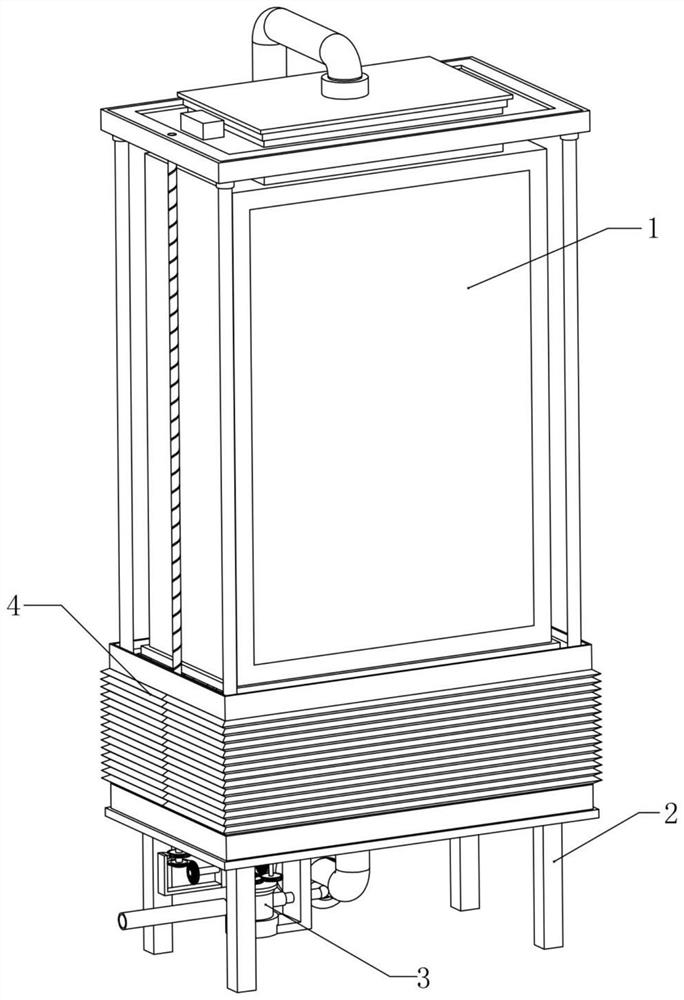
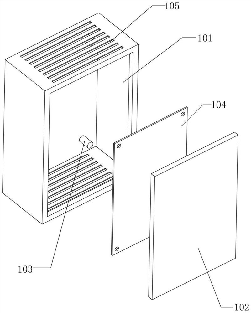
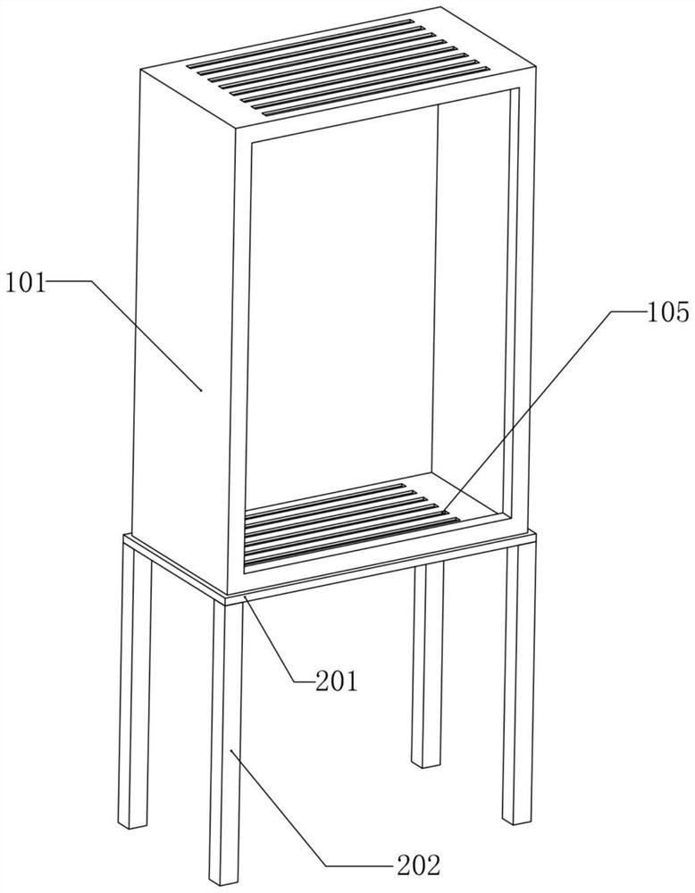
[0043] Example: such as figure 1 , figure 2 , image 3 , Figure 4 , Figure 5 , Image 6 , Figure 7 , Figure 8 , Figure 9 , Figure 10 , Figure 11 , Figure 12 , Figure 13 with Figure 14 Shown is a control device for secondary water supply with self-protection, the cabinet shell assembly 1 is the main body of the control equipment, the top of the base assembly 2 is fixedly connected to the bottom surface of the cabinet shell assembly 1, and the hydrodynamic chamber 302 is arranged in the cabinet shell Below the assembly 1, and the hydrodynamic chamber 302 communicates with the waterway of the secondary water supply, the hydrodynamic impeller 303 is screwed into the inner cavity of the hydrodynamic chamber 302, the heat dissipation chamber 306 is fixedly connected to the top inner surface of the base assembly 2, and the heat dissipation chamber 306 communicates with the air in the cabinet housing assembly 1. An axial flow impeller 307 is screwed horizontally...


PUM


Abstract

The invention provides secondary water supply control equipment with protection, which comprises a cabinet shell assembly, a base assembly, a hydrodynamic heat dissipation assembly and a linkage protection assembly, and is integrally fixed on an operation plane through the base assembly; ventilation holes are formed in the upper face and the lower face of a main cabinet body in the cabinet shell assembly, a heat dissipation cavity in the hydrodynamic heat dissipation assembly is connected into the ventilation holes circularly connected to the upper face and the lower face of the main cabinet body, an axial flow impeller used for heat dissipation is in transmission communication with a secondary water supply pipeline, and a cooling spiral pipe is connected to the outer portion of an air return pipe in a sleeving mode. Air containing heat in the main cabinet body can be circularly cooled through water flow power; meanwhile, a linkage protection assembly is arranged outside the cabinet shell assembly, a telescopic cover in the linkage protection assembly can automatically move up and down, a secondary water supply pipeline is used as a power source for movement, after the rainwater detection module detects the rainwater weather, a signal can be sent out to enable the telescopic cover to move from bottom to top, the cabinet shell assembly is completely arranged in the telescopic cover in a covering mode, and the safety of the cabinet is improved. The protection effect is good.

Description

technical field [0001] The invention relates to a control device for secondary water supply, in particular to a control device for secondary water supply with self-protection. Background technique [0002] In the process of rapid development of modern urbanization, high-rise buildings have become the main building form of the city, and with the increase in the number of high-rise buildings, normal pressure water supply cannot meet the water needs of high-rise building users, which also makes the proportion of secondary water supply continuously rising trend. [0003] However, the current secondary water supply lacks special management and maintenance, and there are many problems, which put forward higher requirements for the automatic operation and management of residents' secondary water supply facilities. By adopting advanced control equipment, the operation and management level of secondary water supply facilities for residents can be improved, energy saving can be achie...

Claims


Application Information

Patent Timeline
Patent Type & Authority Applications(China)
IPC IPC(8): H05K7/20H05K5/02F03B13/00
CPCH05K5/0217H05K7/20218F03B13/00
Inventor 程立高晓昆刘新贵
Owner 重庆昕晟环保科技有限公司
Why Eureka
Try Eureka