Plate punching feeding-discharging equipment and operation method thereof

A sheet metal and equipment technology, applied in the field of sheet metal punching and loading and unloading equipment, can solve problems such as safety risks, manpower occupation, and inconvenient operation

Pending Publication Date: 2020-10-09
厦门柔性电子研究院有限公司 +2
View PDF0 Cites 1 Cited by
  • Summary
  • Abstract
  • Description
  • Claims
  • Application Information

AI Technical Summary

Problems solved by technology

[0002] Sheet metal, such as solder sheet, needs to be punched into several small pieces by punching a large piece of sheet metal. At present, the processing method of sheet metal is basically to complete the punching of sheet metal by manually operating a punching machine. The loading and unlo

Method used


Image

  • Plate punching feeding-discharging equipment and operation method thereof
  • Plate punching feeding-discharging equipment and operation method thereof
  • Plate punching feeding-discharging equipment and operation method thereof

Examples


Embodiment Construction

[0042] In order to further explain the technical solution of the present invention, the present invention will be described in detail below through specific examples.

[0043]In describing the present invention, it should be understood that the terms "center", "longitudinal", "transverse", "upper", "lower", "front", "rear", "left", "right", " Vertical", "horizontal", "top", "bottom", "inner", "outer" and other indication orientations or positional relationships are based on the orientations or positional relationships shown in the drawings, and are only for the convenience of describing the present invention and simplifying Describes, but does not indicate or imply that the device or element referred to must have a specific orientation, be constructed in a specific orientation, and operate in a specific orientation, and therefore should not be construed as limiting the invention. In the description of the present invention, unless otherwise specified, "plurality" means two or ...


PUM


Abstract

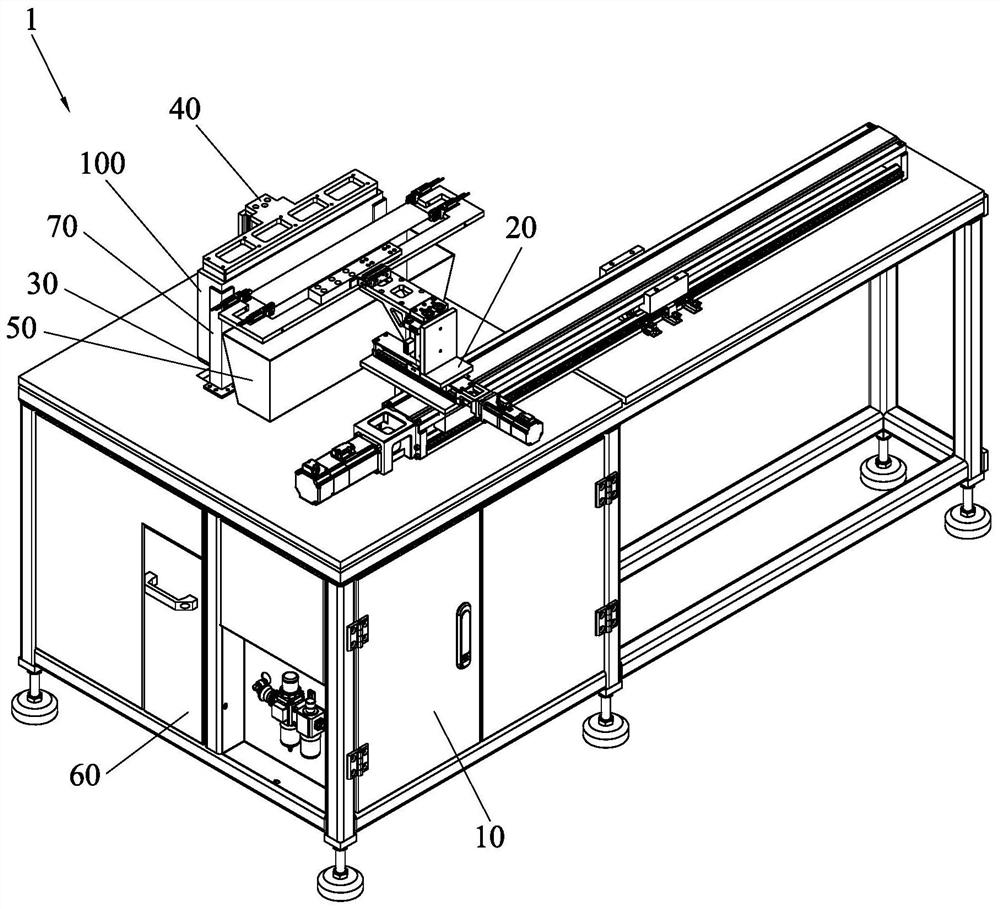
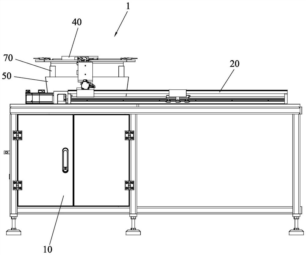
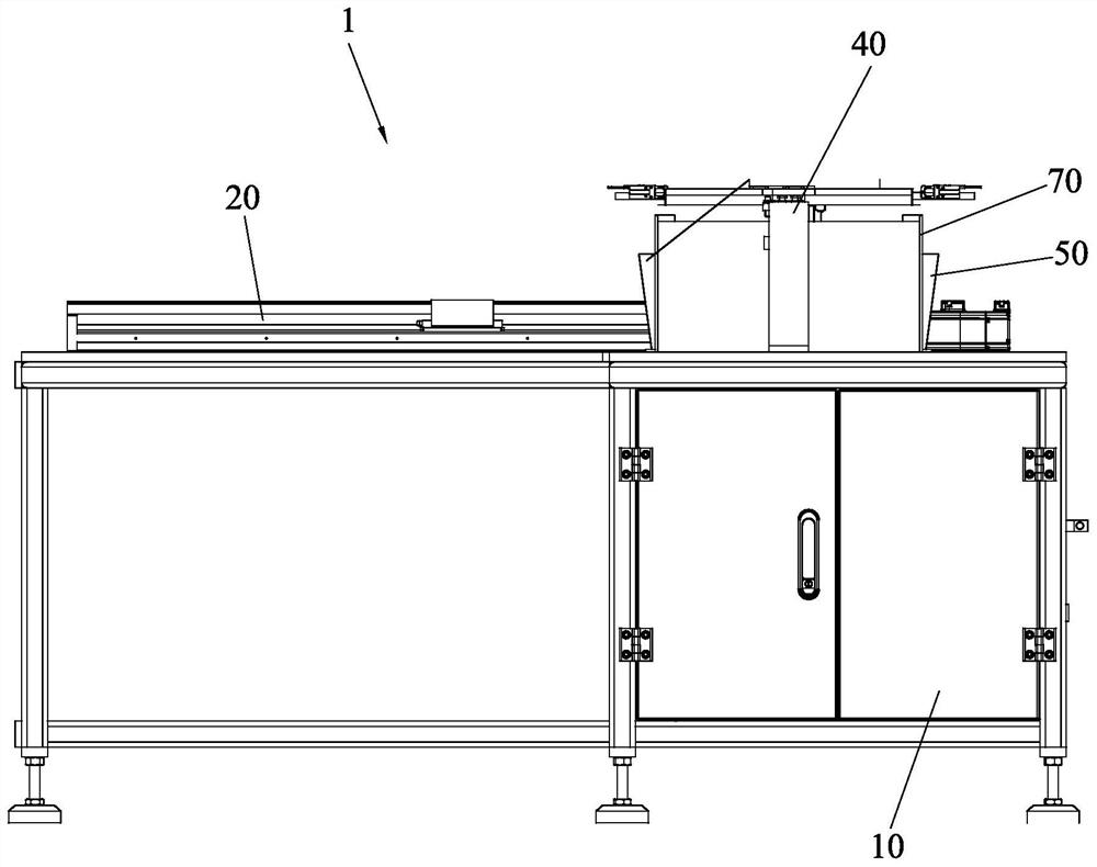
The invention discloses plate punching feeding-discharging equipment. The equipment comprises a rack, a manipulator mechanism, a lifting mechanism, a hoisting mechanism, a dropping slide rail and a waste box, wherein the lifting mechanism is arranged on the rack, a material loading table is arranged at the top of the lifting mechanism, the hoisting mechanism is arranged on the rack and located onone side of the lifting mechanism, a suction cup is arranged at the top end of the lifting mechanism, the bottom face of the suction cup faces the top face of the material loading table of the liftingmechanism, and the manipulator mechanism is arranged on the side, opposite to the lifting mechanism and the hoisting mechanism, of the rack and comprises an X-axis module, a Y-axis module and a clamping module. The X-axis module is fixed to the rack, the Y-axis module is slidably arranged on the X-axis module, and the clamping module is arranged on the Y-axis module in an extensible mode. The dropping slide rail is arranged on the rack and located between the lifting mechanism and the manipulator mechanism, and the waste box is arranged below the dropping slide rail. The equipment can replacemanual feeding and realizes an automatic punching process.

Description

technical field [0001] The invention relates to the technical field of sheet material processing, in particular to a sheet material punching and loading and unloading device. Background technique [0002] Sheet metal, such as solder sheet, needs to be punched into several small pieces by punching a large piece of sheet metal. At present, the processing method of sheet metal is basically to complete the punching of sheet metal by manually operating a punching machine. The loading and unloading operation is done manually, especially when the size of the sheet is long. Manual loading and unloading is inconvenient and the production efficiency is low. One person operates one machine, which takes up a lot of manpower, and manual operation of the punching machine poses safety risks. Contents of the invention [0003] The purpose of the present invention is to overcome the deficiencies of the prior art, and provide a sheet metal punching and loading and unloading equipment and it...

Claims


Application Information

Patent Timeline
IPC IPC(8): B21D28/04B21D28/00B21D43/18B21D43/02B21D43/24
CPCB21D28/00B21D28/04B21D43/027B21D43/18B21D43/24
Inventor 卢开河李山水赵继伟续振林朱石宝陈妙芳
Owner 厦门柔性电子研究院有限公司
Why Eureka
Try Eureka