Efficient pipe chase machine and pipe machining method

A pipe groove machine, an efficient technology, applied in metal processing, metal processing equipment, metal processing machinery parts, etc., can solve problems such as poor matching and low processing efficiency, and achieve the effect of expanding storage space

Pending Publication Date: 2020-10-09
张家港市振原制管有限公司
View PDF0 Cites 2 Cited by
  • Summary
  • Abstract
  • Description
  • Claims
  • Application Information

AI Technical Summary

Problems solved by technology

[0004] One of the purposes of the present invention is to solve the problem of low processing efficiency due to the need for manual operation and the poor matching between the existing processing device and the production line in the prior art when processing pipe fittings

Method used


Image

  • Efficient pipe chase machine and pipe machining method
  • Efficient pipe chase machine and pipe machining method
  • Efficient pipe chase machine and pipe machining method

Examples


Embodiment 1

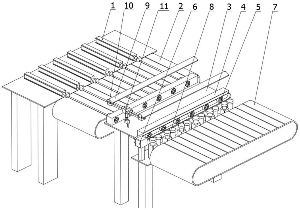
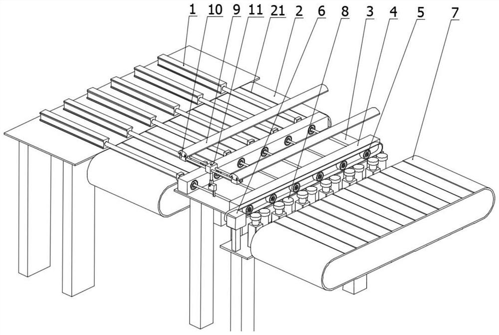
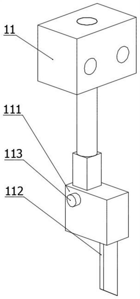
[0077] A high-efficiency pipe groove machine, wherein, such as figure 1 , 2 As shown, it includes: a pushing device 1 , a first conveying mechanism 2 , a rotating clamping mechanism 3 , a rotating device 6 , a displacement part 10 , a sliding block 11 , a set 111 , and a second conveying mechanism 7 .

[0078] The pushing device 1 can move freely telescopically. The first transfer mechanism 2 is in the right end position of the push mechanism.

[0079] The rotating clamping mechanism 3 is located at the right end of the first conveying mechanism 2 , and the rotating clamping mechanism 3 includes a mounting seat 4 , a bearing (not shown), and a clamping assembly 5 . There are at least two mounting seats 4 , the mounting seats 4 have accommodating spaces, and the accommodating spaces between the mounting seats 4 are aligned with each other. The bearing is provided in the accommodating space.

[0080] The clamping assembly 5 is arranged in the bearing, such as Figure 4-7 As...


PUM


Abstract

The invention discloses an efficient pipe chase machine, and relates to the technical field of pipe machining. The efficient pipe chase machine comprises a pushing device 1, a first conveying mechanism 2, a rotary clamping mechanism 3, a rotating device 6, a displacement part 10, a sliding block 11, a kit 111 and a second conveying mechanism 7. According to the efficient pipe chase machine, firstly, the first conveying mechanism 2 is used for bearing and conveying a pipe in the previous procedure, then the rotating device 6 is started to drive a clamping assembly 5 to drive the pipe to rotate,meanwhile, automatic clamping of the pipe is achieved, then the pipe is machined through the displacement part 10 and the sliding block 11, and finally, the pipe is moved to the second conveying mechanism 7 to be conveyed to the next procedure. According to the efficient pipe chase machine, manual operation is not needed in the feeding, machining and discharging processes, and automatic development is facilitated.

Description

technical field [0001] The invention relates to the technical field of pipe fittings processing, in particular to a high-efficiency pipe groove machine. Background technique [0002] In the machining industry, it is often encountered that annular grooves are processed on pipe fittings, and the processing of annular grooves is mainly for sealing and balancing, and may also be used for positioning, fixing, shock-proof and other functions. [0003] Under the prior art, the machining of annular grooves in the machinery industry is mostly done by turning or milling. However, when fixing the pipe, it is generally clamped by a three-jaw chuck, and then the motor drives the pipe to rotate along its central axis, and then uses a cutting tool such as a turning tool to process the annular groove on the surface of the pipe. However, the use of existing processing devices (lathes or milling machines, etc.) to process annular grooves for pipe fittings has relatively large limitations. Fi...

Claims


Application Information

Patent Timeline
Patent Type & Authority Applications(China)
IPC IPC(8): B23Q3/06B23Q7/00B23Q7/06B23Q1/25
CPCB23Q1/25B23Q3/064B23Q7/00B23Q7/06
Inventor 张建兴邬喜峰侯中华
Owner 张家港市振原制管有限公司
Why Eureka
Try Eureka