Marine microbubble generating device

A micro-bubble generation and bubble technology, which is applied in ship hull, hull design, ship construction, etc., can solve the problems of large jet resistance, large bubble diameter, and increased power consumption of the blower, so as to reduce difficulty, ensure stability, and improve drag reduction. rate effect

Active Publication Date: 2020-10-09
WUHAN UNIV OF TECH
View PDF6 Cites 2 Cited by
  • Summary
  • Abstract
  • Description
  • Claims
  • Application Information

AI Technical Summary

Problems solved by technology

[0004] Existing microbubble drag reduction studies mostly focus on ship type design, generator layout, etc., but not much research on bubble generators. Most of them use the porous plate blowing method to generate bubbles. This method is more convenient to process, but the use of sintered porous The bubbles ejected from the adjacent micropores of the plate affect each other and aggregate, and the diameter of the generated bubbles is relatively large; at the same time, the air jet resistance is large, and the power consumption of the blower increases, and the effect is not ideal, which hinders the practical application of microbubble drag reduction technology

Method used


Image

  • Marine microbubble generating device
  • Marine microbubble generating device
  • Marine microbubble generating device

Examples


Embodiment Construction

[0024] In order to have a clearer understanding of the technical features, purposes and effects of the present invention, the specific implementation manners of the present invention will now be described in detail with reference to the accompanying drawings.

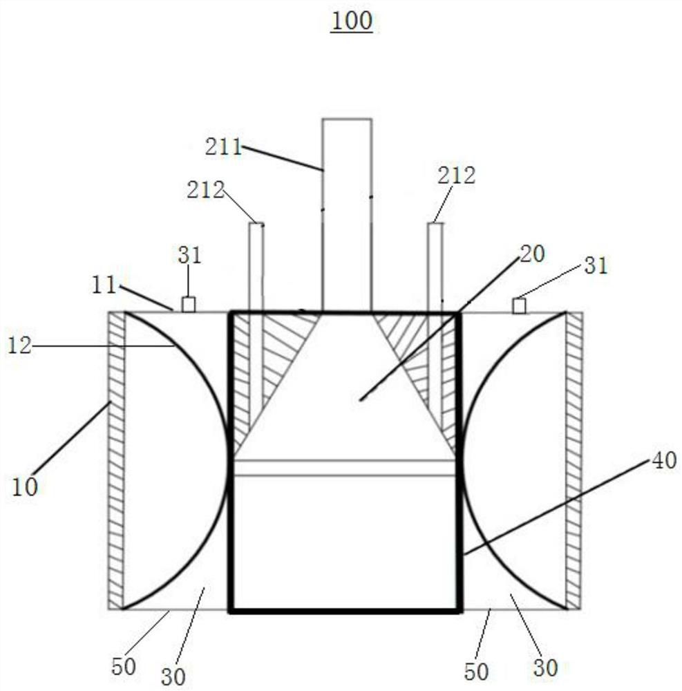
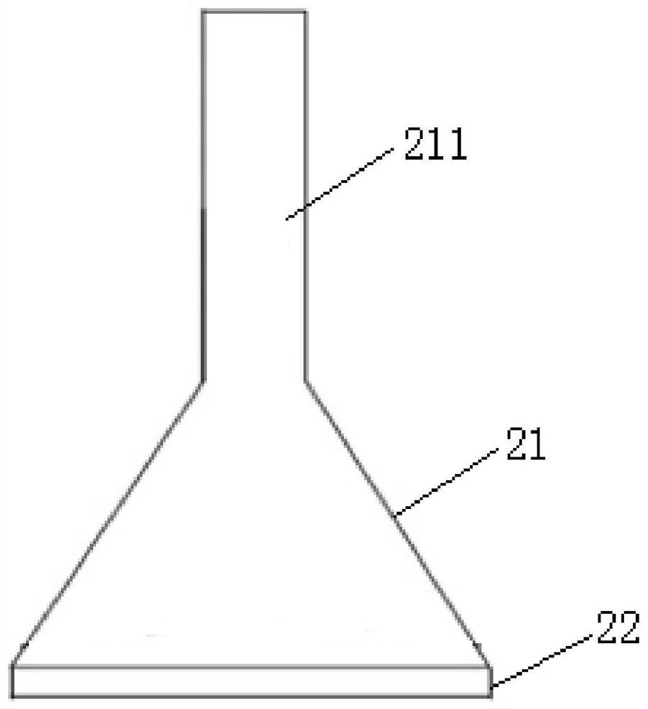
[0025] Such as Figure 1-2 As shown, a microbubble generating device 100 provided by the present invention includes a casing 10 , a gas channel 20 rotatably installed in the casing 10 , and a cover 40 . The upper end of the housing 10 is provided with an end cap 11 for sealing, the lower end is a bubble nozzle 50 connected to the outside, and the inner side of the housing 10 is provided with an inwardly protruding arc-shaped wall 12 . The gas flow channel 20 includes a variable diameter wall surface 21 whose diameter gradually increases along the gas flow direction and an equal diameter wall surface 22 arranged at the lower end of the variable diameter wall surface 21. There are exhaust holes 221 , and the equal-diamet...


PUM


Abstract

The invention relates to a microbubble generating device which comprises a shell, a gas flow channel and a cover body. The upper end of the shell is sealed and the lower end is a bubble nozzle; the gas flow channel comprises a variable-diameter wall surface and an equal-diameter wall surface, a gas inlet is formed in the top end of the variable-diameter wall surface, N groups of exhaust holes areuniformly formed in the equal-diameter wall surface in the circumferential direction, N is an even number, and the diameters of the two groups of exhaust holes symmetrical about the circle center aredifferent; the gas-liquid mixing wall surface of the cover body is arranged outside the gas flow channel, the upper end and the lower end of the gas-liquid mixing wall surface are sealed, and a liquidflow channel which is gradually shrunk and then gradually expanded is formed between the gas-liquid mixing wall surface and the shell; the gas-liquid mixing wall face is provided with two openings symmetrical about the circle center at the same height of the exhaust holes, each opening corresponds to one set of exhaust holes, and when the gas flow channel rotates to a certain angle, the two openings correspond to the two sets of exhaust holes with different diameters respectively. High-quality microbubbles with smaller diameters can be generated through simultaneous gas injection of the two sets of exhaust holes, and the drag reduction rate is further increased.

Description

technical field [0001] The invention relates to the technical field of ship air curtain drag reduction, in particular to a marine microbubble generating device. Background technique [0002] For a long time, ship workers have taken improving propulsion efficiency and saving fuel as the main goals of their efforts. In the scientific and economic way of ship energy saving, drag reduction and energy saving has always been the main theme advocated. Ship drag reduction technology can significantly reduce energy consumption, save energy and reduce emissions, and increase the speed of ship navigation, which has important economic and military benefits. Therefore, it has been It is one of the hot spots of ship engineering research. [0003] Ship air curtain drag reduction technology is to spray micro-bubbles at the bottom of the ship, use micro-bubbles to separate the bottom of the ship from water, and change the contact between the ship and water into contact with the mixture of m...

Claims


Application Information

Patent Timeline
Patent Type & Authority Applications(China)
IPC IPC(8): B63B1/38
CPCB63B1/38B63B2001/387B63B2001/385Y02T70/10
Inventor 朱汉华王锡涵张亚卿徐庚辉
Owner WUHAN UNIV OF TECH
Why Eureka
Try Eureka