Packaging tube structure for packaging micro-mini integrated circuits

A technology for integrated circuits and packaging tubes, which is applied in the field of packaging tube structures for packaging micro-miniature integrated circuits to prevent interlacing with each other.

Inactive Publication Date: 2020-10-09
龙岩市云惠企科技服务有限公司
View PDF9 Cites 0 Cited by
  • Summary
  • Abstract
  • Description
  • Claims
  • Application Information

AI Technical Summary

Problems solved by technology

[0003] The structure of the packaging tube for packaging micro-miniature integrated circuits is generally simple in structure. During the packaging process, the integrated circuits are often placed one by one into the inside of the packaging tube, so that the integrated circuits are superimposed and interlaced together. The existing packaging micro-miniature integrated circuits The structure of the packaging tube is not easy to separate the integrated circuits, causing the integrated circuits to be interlaced with each other

Method used


Image

  • Packaging tube structure for packaging micro-mini integrated circuits
  • Packaging tube structure for packaging micro-mini integrated circuits
  • Packaging tube structure for packaging micro-mini integrated circuits

Examples


Embodiment 1

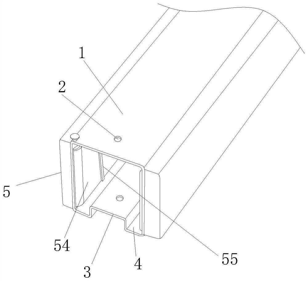
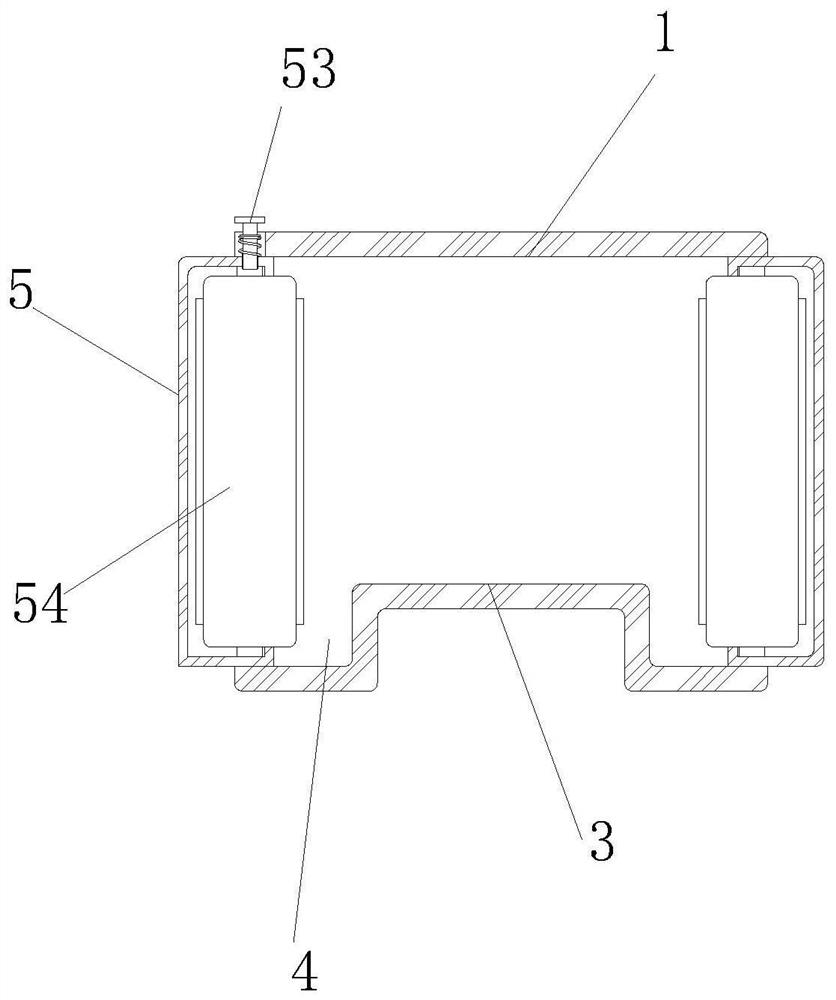
[0029] see figure 1 and figure 2 , the present invention provides a packaging tube structure for packaging micro-integrated circuits through improvement, including a tube body 1, a fixing hole 2, a guide rail 3, a chute 4 and a separation guide mechanism 5, and the front end of the tube body 1 is opposite to the upper and lower sides. A fixing hole 2 is provided, and the separation guide mechanism 5 is installed and fixed on the inner left end of the pipe body 1 and is fixedly connected.

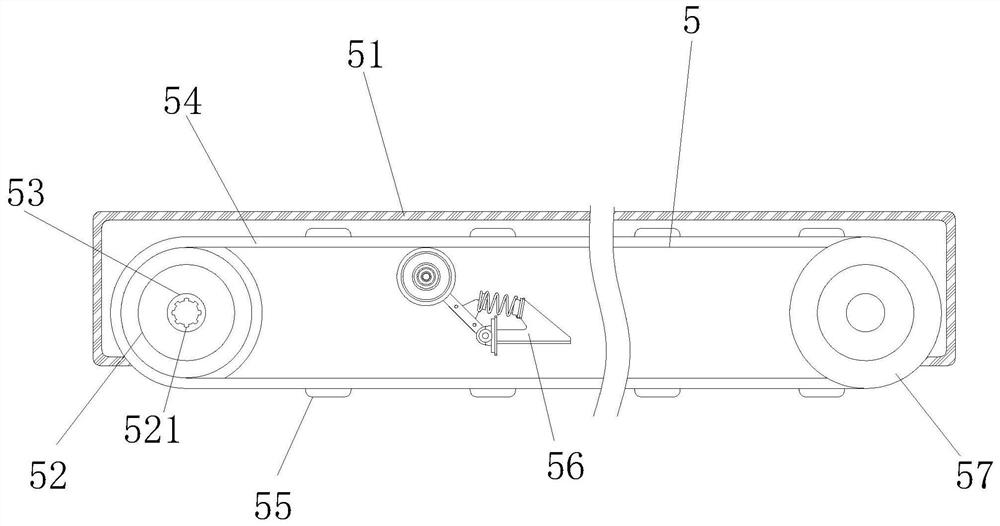
[0030] see image 3 , the present invention provides a packaging tube structure for packaging micro-integrated circuits through improvement. The separation guide mechanism 5 includes a fixed frame 51, a first runner 52, a rotating mechanism 53, a belt 54, a dividing plate 55, and a tensioning mechanism 56. And the second runner 57, the fixed frame 51 is fixedly connected with the inner left end of the pipe body 1, the first runner 52 is connected with the inner left end of the fixed frame...

Embodiment 2

[0034] The present invention provides a packaging tube structure for packaging micro-miniature integrated circuits through improvement. The center lines of the knob 531, the rotating shaft 532, the limit block 533 and the return spring 534 are in the same vertical direction, which is beneficial to make the rotating shaft 532 For the function of smooth rotation, a groove 521 is provided in the middle of the first runner 52 , and the protrusion 535 is embedded inside the groove 521 , which is beneficial to drive the first runner 52 to rotate.

[0035] The present invention provides a packaging tube structure for packaging micro-miniature integrated circuits through improvement, and its working principle is as follows;

[0036] First, before use, the packaging tube structure for packaging micro-miniature integrated circuits is placed horizontally, so that the tube body 1 can fix and support the packaging tube structure;

[0037]Second, when in use, the integrated circuits are pla...


PUM


Abstract

The invention discloses a packaging tube structure for packaging micro-mini integrated circuits. The packaging tube structure comprises a tube body, a fixing hole, a guide rail, a sliding groove and aseparation guide mechanism. The separation guide mechanism is arranged inside the tube body to push the integrated circuits to the inside of the tube body. The integrated circuits can be separated bypartitions, and with the addition of the integrated circuits, the belt can be driven on the upper ends of a first runner and a second runner. The integrated circuits can be transported smoothly, andthe advantages of placing integrated circuits separately to prevent the integrated circuits from interlacing each other can be achieved. Through arranging a rotating mechanism inside the separation guide mechanism, a knob is pressed downwards, so that a bump at the bottom of a rotating shaft is embedded inside a groove. Then the knob is rotated, so that the rotating shaft drives the first runner to rotate through a convex block, achieving the advantage of being able to quickly drive the first runner to rotate.

Description

technical field [0001] The invention relates to the related field of packaging of electronic components, in particular to a packaging tube structure for packaging micro-miniature integrated circuits. Background technique [0002] With the development of electronic technology, the early electronic industry standard SJ / T10147-91 can no longer meet the requirements of modern technology. In recent years, integrated circuit packaging and testing companies have designed the SSOP series packaging tube cross-section according to the external dimensions of SSOP integrated circuits. structure to package SSOP ICs. [0003] The structure of the packaging tube for packaging micro-miniature integrated circuits is generally simple in structure. During the packaging process, the integrated circuits are often placed one by one into the inside of the packaging tube, so that the integrated circuits are superimposed and interlaced together. The existing packaging micro-miniature integrated circ...

Claims


Application Information

Patent Timeline
Patent Type & Authority Applications(China)
IPC IPC(8): B65D25/02B65D25/52B65D85/90B65G15/58B65G23/04B65G15/08B65G15/32B65G23/44B65G49/06
CPCB65D25/02B65D25/52B65D2585/86B65G15/08B65G15/32B65G15/58B65G23/04B65G23/44B65G49/06
Inventor 蔡少辉陈博文
Owner 龙岩市云惠企科技服务有限公司
Why Eureka
Try Eureka