Supercharge Your Innovation With Domain-Expert AI Agents!

Automatic PCB feeding and discharging machine

A technology for automatic loading and unloading of PCB boards, applied to conveyors, conveyor objects, laminated printed circuit boards, etc., can solve the problems of small size and ineffective transportation of PCB automatic loading and unloading machines, and achieve convenient manufacturing Effect

Active Publication Date: 2020-10-09
宁夏隆基宁光仪表股份有限公司
View PDF6 Cites 0 Cited by
  • Summary
  • Abstract
  • Description
  • Claims
  • Application Information

AI Technical Summary

Problems solved by technology

[0004] Based on the technical problem that the existing PCB board automatic loading and unloading machine is too small to be effectively transported, the present invention proposes a PCB board automatic loading and unloading machine

Method used


Image

  • Automatic PCB feeding and discharging machine
  • Automatic PCB feeding and discharging machine
  • Automatic PCB feeding and discharging machine

Examples


Embodiment 1

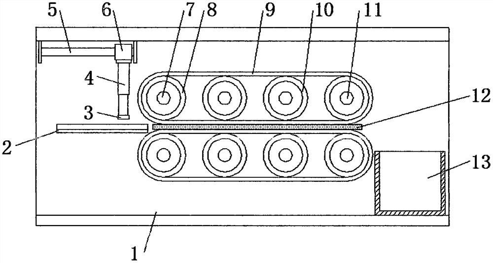
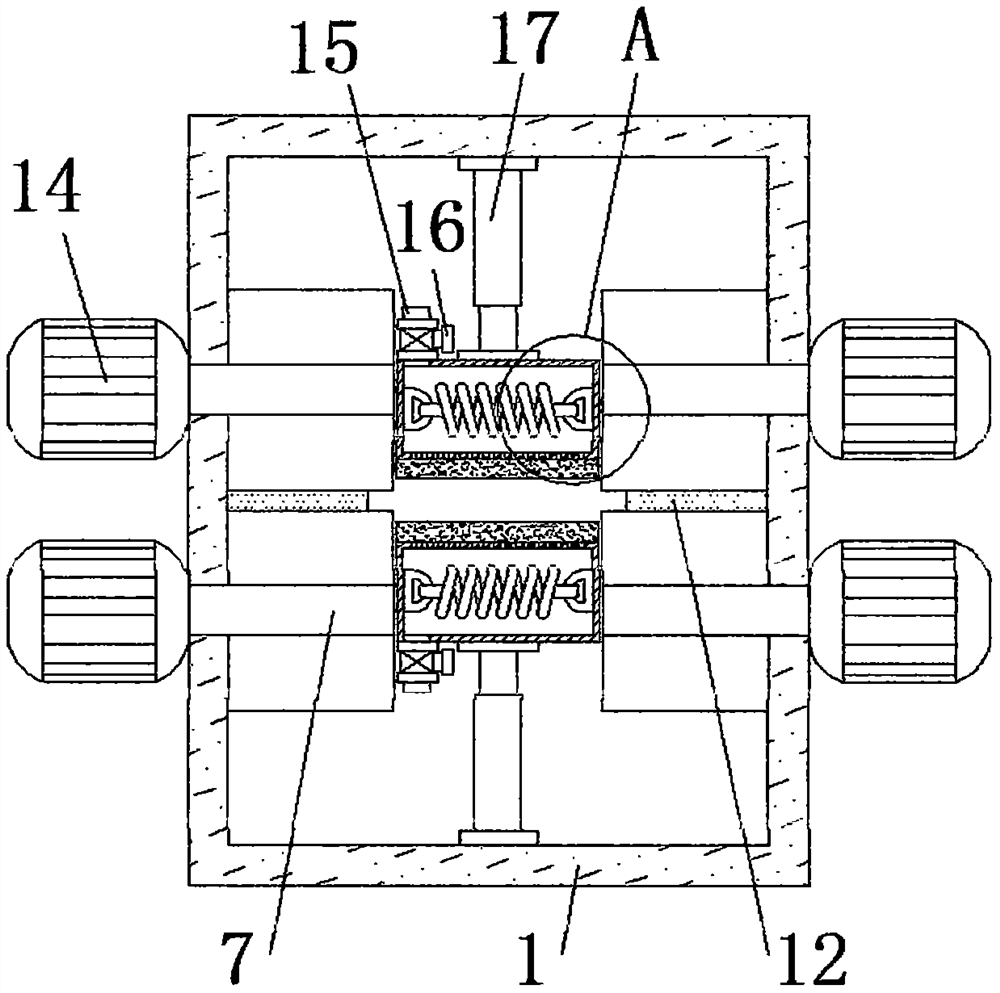
[0027] refer to Figure 1-4 , a PCB board automatic loading and unloading machine, comprising a fixed frame 1, one side of the top inner wall of the fixed frame 1 is provided with a push mechanism, two motors 14 and four motors 14 are fixed on the outer walls of both sides of the fixed frame 1 by bolts One end of the output shaft is connected with a transmission shaft 7 by a key, and one end of the four transmission shafts 7 is located inside the fixed frame 1, and the peripheral outer wall of the transmission shaft 7 is sleeved with a driving wheel 8, and the inner walls of both sides of the fixed frame 1 are provided with A plurality of rotating shafts 11 are plugged in, and the rotating shafts 11 and the transmission shaft 7 are located on the same horizontal line, auxiliary wheels 10 are sleeved on the outer peripheral walls of the rotating shafts 11, and a conveyor belt 9 is sleeved on the outer walls of the driving wheel 8 and the auxiliary wheels 10, There is a gap betw...

Embodiment 2

[0032] refer to Figure 5 , an automatic loading and unloading machine for PCB boards. Compared with Embodiment 1, this embodiment is fixed with a fixed plate 23 by bolts on one side of the fixed frame 1, and an air suction pump is fixed by bolts on one side of the outer wall of the fixed plate 23. 24. The output end of the air pump 24 is facing the conveyor belt 9, and the air pump 24 is located above the collection tank 13.

[0033] During use, when the PCB board is out of the range of the conveyor belt 9, start the air pump 24 to pump air, so as to facilitate the discharging of the PCB board and ensure that the PCB board can stably fall into the collection tank 13 inside.


PUM


Abstract

The invention discloses an automatic PCB feeding and discharging machine. Aiming at the problems that the size is too small and effective transportation cannot be achieved, the following scheme is provided. The automatic PCB feeding and discharging machine comprises a fixing frame, a pushing mechanism is arranged on one side of the inner wall of the top of the fixing frame, and two motors are fixed to the outer walls of the two sides of the fixing frame through bolts; one ends of output shafts of the four motors are all in key connection with transmission shafts, one ends of the four transmission shafts are all located in the fixing frame, the circumferential outer walls of the transmission shafts are sleeved with driving wheels, a plurality of rotating shafts are inserted into the inner walls of the two sides of the fixing frame, and the rotating shafts and the transmission shafts are located on the same horizontal line; and the circumferential outer walls of the rotating shafts are sleeved with auxiliary wheels, and the outer walls of the driving wheels and the outer walls of the auxiliary wheels are sleeved with conveying belts. According to the automatic PCB feeding and discharging machine, by means of four sets of conveying belt mechanisms, a gap is reserved between every two adjacent conveying belts and is consistent with the width and the thickness of a PCB, the movementkinetic energy of the conveying belts can be conveniently used for driving the PCB to be conveyed, and then automatic feeding and discharging are carried out.

Description

technical field [0001] The invention relates to the technical field of feeding devices, in particular to an automatic loading and unloading machine for PCB boards. Background technique [0002] The Chinese name of PCB is printed circuit board, also known as printed circuit board. It is an important electronic component, a support for electronic components, and a carrier for electrical connections of electronic components. Since it is made by electronic printing, it is Named printed circuit board, printed circuit boards need to be loaded and unloaded during production, so it is necessary to use an automatic PCB board loading and unloading machine. [0003] At present, most of the existing automatic loading and unloading machines for PCB boards on the market have the following deficiencies: the PCB board is too small to be effectively transported, which in turn affects the production efficiency of the PCB board, and the existing patents are not easy to solve such problems. The...

Claims


Application Information

Patent Timeline
Patent Type & Authority Applications(China)
IPC IPC(8): B65G15/14B65G47/04H05K3/00
CPCB65G15/14B65G47/04H05K3/0058H05K2203/06
Inventor 柳霞陆开洪梁学柱林婷刘静
Owner 宁夏隆基宁光仪表股份有限公司
Features
  • R&D
  • Intellectual Property
  • Life Sciences
  • Materials
  • Tech Scout
  • Unparalleled Data Quality
  • Higher Quality Content
  • 60% Fewer Hallucinations
Learn More