A rust removal device for steel bars for construction

A technology for building and steel bars, which is applied in the field of steel bar rust removal devices for building, can solve the problems of repeated manual replacement, and achieve the effect of reducing manual operations.

Active Publication Date: 2022-07-08
CHINA CONSTR FIFTH ENG DIV CORP LTD
View PDF12 Cites 0 Cited by
  • Summary
  • Abstract
  • Description
  • Claims
  • Application Information

AI Technical Summary

Problems solved by technology

[0005] In order to overcome the shortcomings of manual spraying of rust remover to rotate the steel bar and repeated replacement of the steel bar in the process of manual rust removal, the technical problem is to provide an automatic rotating steel bar that automatically sprays the rust remover on the steel bar, And can automatically replace the steel bar construction steel derusting device

Method used


Image

  • A rust removal device for steel bars for construction
  • A rust removal device for steel bars for construction
  • A rust removal device for steel bars for construction

Examples


Embodiment 1

[0047] A rust removal device for steel bars for construction, such as figure 1 As shown, it includes a base 1, a first support column 2, a bottom plate 3, a rotary movement mechanism 4, a loosening mechanism 5 and a collection frame 6. The left and right sides of the base 1 are provided with two first support columns 2, four fourth A bottom plate 3 is connected between the top of the support column 2, a rotary movement mechanism 4 is provided on the front and rear sides of the bottom plate 3, a loosening mechanism 5 is provided on the front and rear sides of the bottom plate 3, and the loosening mechanism 5 is connected with the rotary movement mechanism 4, and the left side of the bottom plate 3 is provided with a loosening mechanism 5. A collection frame 6 is placed.

[0048] When it is necessary to derust the steel bars, manually move the parts of the rotating moving mechanism 4 to both sides, place the steel bars on the parts of the rotating moving mechanism 4, and then re...

Embodiment 2

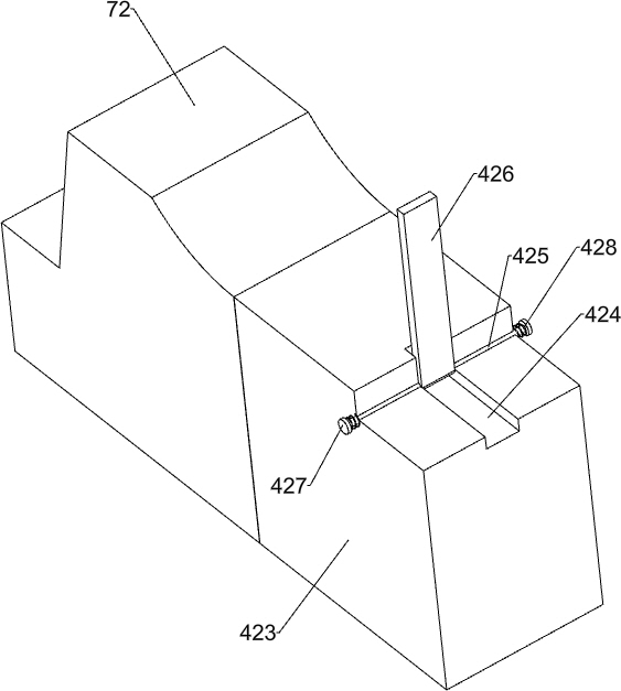
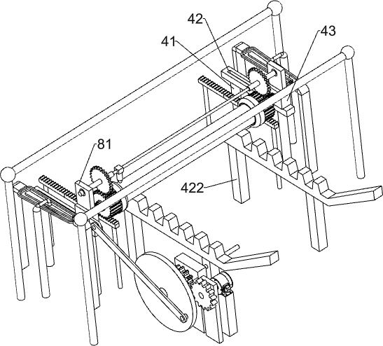
[0050] Specifically, as Figure 2-5 As shown, the rotational movement mechanism 4 includes a second support column 41, a slide rail 42, a slider 43, a first shaft 44, a shaft sleeve 45, a third support column 46, a rack 47, a first gear 48, a collet 49, The first elastic member 410, the sector block 411, the first bearing seat 412, the first transmission shaft 413, the second gear 414, the turntable 415, the connecting rod 416, the second bearing seat 417, the second shaft 418, the third gear 419, The mounting block 420, the motor 421, the first support block 422, the spacer block 423, the third shaft 425, the stopper 426, the first round block 427 and the second elastic member 428, two are installed on the front and rear sides of the left part of the bottom plate 3 For the second support column 41, a slide rail 42 is arranged between the tops of the second support columns 41 on the same side. A slider 43 is slidably arranged in the slide rail 42, and a first shaft 44 is rotat...

Embodiment 3

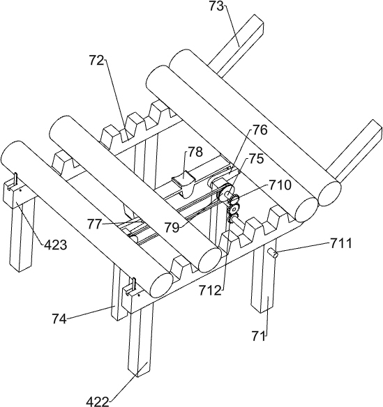
[0055] refer to Figure 6-8 As shown in the figure, it also includes a feeding mechanism 7, and the feeding mechanism 7 includes a second support block 71, a feeding rail 72, a flat guide rail 73, a third support block 74, a second transmission shaft 75, a crank 76, a second The connecting shaft 77 , the feeding block 78 , the belt transmission device 79 , the third connecting shaft 710 , the third transmission shaft 711 and the fourth gear 712 , the right part of the bottom plate 3 is provided with a second support block 71 on both the front and rear sides, and the second support block A feeding rail 72 is installed on the top of the 71, the left part of the feeding rail 72 is connected with the right part of the cushion block 423, the right end of the feeding rail 72 is provided with a flat guide rail 73, and two third support blocks 74 are installed in the middle of the bottom plate 3, and the upper part of the third support block 74 The second transmission shaft 75 is rota...


PUM


Abstract

The invention relates to a rust removal device, in particular to a rust removal device for steel bars for construction. Technical problem: To provide a steel rust removal device for construction that can automatically rotate the steel bar, automatically spray the rust remover on the steel bar, and can automatically replace the steel bar. The technical scheme of the present invention is: a rust removal device for steel bars for construction, comprising: a base, at least two first support columns are installed on the left and right sides of the base, and a bottom plate is provided on the top of the first support column; a rotary movement mechanism, the bottom plate The front and rear sides are equipped with rotating and moving mechanisms, and the front and rear sides of the bottom plate are provided with loosening mechanisms. The invention can drive the steel bars to move and rotate automatically through the rotating moving mechanism, which is convenient for spraying the rust remover on the steel bars. , Through the blanking mechanism, the automatic replacement of the steel bar can be realized, and there is no need to manually take the steel bar repeatedly, which reduces the manual operation.

Description

technical field [0001] The invention relates to a rust removal device, in particular to a rust removal device for steel bars for construction. Background technique [0002] In the construction industry, steel bars and concrete structures are usually used. However, steel bars are easily rusted when placed on a construction site for a long time. If rusted steel bars are used for construction, the rust will expand, causing concrete to crack, affecting the safety and quality of the entire building. , Therefore, all the rust on the steel bars must be removed before using the steel bars. At present, the rust is removed by spraying the rust remover. The worker needs to spray the rust remover on the surface of the steel bars while turning the steel bars. After the rebar, workers need to replace another rebar for spraying. [0003] Patent CN110625262A discloses a steel bar rust removal equipment, which includes a base, a collection frame, a pillar, a horizontal plate and other compo...

Claims


Application Information

Patent Timeline
Patent Type & Authority Patents(China)
IPC IPC(8): C23G3/02
CPCC23G3/023Y02P70/10
Inventor 唐中辉刘传雄黄宝伟温冬梅
Owner CHINA CONSTR FIFTH ENG DIV CORP LTD
Why Eureka
Try Eureka