Pier beam buffer structure and anti-seismic bridge

A structure, pier and beam technology, applied in the field of pier beam buffer structure and seismic bridges, can solve problems such as large earthquake response and damage to bridge structures, and achieve the effects of reducing lateral displacement, strengthening bridge structures, and improving lateral seismic performance.

Pending Publication Date: 2020-10-09
CHINA HYDROELECTRIC ENGINEERING CONSULTING GROUP CHENGDU RESEARCH HYDROELECTRIC INVESTIGATION DESIGN AND INSTITUTE +1
View PDF0 Cites 0 Cited by
  • Summary
  • Abstract
  • Description
  • Claims
  • Application Information

AI Technical Summary

Problems solved by technology

[0004] The purpose of the present invention is to: in the high-intensity earthquake area that exists in the prior art, due to the effect of the earthquake force, the bridge will produce a large seismic response, and the main girder and the bridge pier may have a large displacement or even separation, which will damage the bridge. Structural problems, providing a pier-beam buffer structure and an earthquake-resistant bridge with better seismic performance

Method used


Image

  • Pier beam buffer structure and anti-seismic bridge
  • Pier beam buffer structure and anti-seismic bridge
  • Pier beam buffer structure and anti-seismic bridge

Examples


Embodiment 1

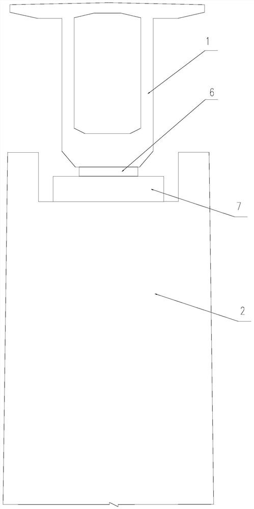
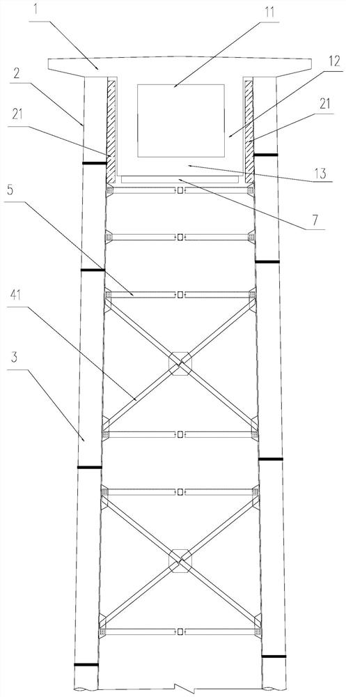
[0052] Such as figure 2 As shown, a pier-beam buffer structure includes a bridge pier 2 and a main girder 1, the main girder 1 is a box girder, and the main girder 1 includes a top plate 11, a web 12 and a bottom plate 13, and the top plate 11 and the The bottom plate 13 is relatively arranged, the web 12 is arranged between the top plate 11 and the bottom plate 13, the top of the pier 2 is provided with an installation groove, and the main girder 1 is located in the installation groove. Specifically, the The top surface of the pier 2 is flush with the web 12, so that the web 12 is completely contained in the pier 2, so that an anti-shock cushion is provided between the main girder 1 and the pier 2 in the transverse direction The block 21 utilizes the buffering and anti-collision effect of the shockproof cushion block 21 to reduce the mutual collision and extrusion between the main girder 1 and the bridge pier 2 under the earthquake force, and consume the collision energy. R...

Embodiment 2

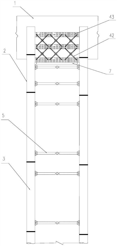
[0057] Such as Figure 2-Figure 8 As shown, a kind of anti-seismic bridge comprises main girder 1, bridge pier 2 and bearing platform 8, and the top surface of described pier 2 is higher than the bottom surface of described main girder 1, and the top of described pier 2 is provided with installation groove, and described main pier The beam 1 is located in the installation groove, and an anti-vibration cushion block 21 is arranged between the main beam 1 and the pier 2 in the transverse direction.

[0058] The platform 8 is provided with a reserved groove, the bottom of the pier 2 is located in the reserved groove, and concrete is poured in the reserved groove. The pier 2 includes four vertical steel pipes 3, the four steel pipes 3 are distributed on the four corners of the rectangle, and the part of the steel pipes 3 located in the reserved groove is provided with several second through holes 92 .

[0059] The bottom of the steel pipe 3 is welded with a pressure-bearing plat...


PUM


Abstract

The invention relates to the technical field of bridge structures, and particularly relates to a pier beam buffer structure and an anti-seismic bridge. The pier beam buffer structure comprises a pierand a main beam; the top face of the pier is higher than the bottom face of the main beam; a mounting groove is formed in the top of the pier; the bottom of the main beam is located in the mounting groove, and shockproof buffer cushion blocks are arranged between the two sides of the main beam and the mounting groove and can reduce mutual collision and extrusion between the main beam and the pierunder the action of earthquake force; the anti-seismic bridge comprises a main beam, piers and a bearing platform; the main beam is connected with the piers through the pier beam buffer structure; thebottoms of steel pipes are connected with bearing plates; a plurality of rib plates are arranged between the bearing plates and the steel pipes; each rib plate is provided with a plurality of first through holes; the bearing platform is provided with a preformed groove; the bottoms of the piers are located in the preformed groove, and concrete is poured into the preformed groove, so that the piers and the bearing platform are connected more reliably, the stability of the bottoms of the piers is enhanced, and the safety and stability of the bridge structure are improved.

Description

technical field [0001] The invention relates to the technical field of bridge structures, in particular to a pier-beam buffer structure and an anti-seismic bridge. Background technique [0002] The bridge pier is a building that supports the bridge span structure and transmits the load to the foundation. It not only needs to bear all the loads transmitted by the bridge span structure, but also directly bears various loads such as earth pressure or water flow impact, so the bridge pier itself has sufficient strength. , rigidity and stability, the solid structure of stone masonry, concrete or steel tube concrete is generally adopted. [0003] Such as figure 1 As shown, in a common bridge structure, the main girder 1 is arranged above the support 6, the top surface of the pier 2 is provided with a pad stone 7, the support 6 is connected with the pad stone 7, and the support 6 is used to reliably transfer the main girder 1 and the load borne by the main girder 1 to the pier 2 ...

Claims


Application Information

Patent Timeline
Patent Type & Authority Applications(China)
IPC IPC(8): E01D19/00E01D19/02E01D1/00
CPCE01D1/00E01D19/00E01D19/02
Inventor 傅支黔王建张彩楼梁健李成君钟川剑王戈康玲游选成柏山
Owner CHINA HYDROELECTRIC ENGINEERING CONSULTING GROUP CHENGDU RESEARCH HYDROELECTRIC INVESTIGATION DESIGN AND INSTITUTE
Why Eureka
Try Eureka