
Steel bar binding system and steel bar binding method

A steel bar and node technology, which is applied in the steel bar binding system and the field of steel bar binding, can solve the problems of uncontrollable binding quality, inconvenient carrying and operation, and high labor intensity, so as to improve the efficiency and quality of steel bar binding and improve the quality of steel bar binding. Efficiency, the effect of ensuring the quality of the bundle

Active Publication Date: 2022-06-28
GUANGDONG BOZHILIN ROBOT CO LTD
View PDF9 Cites 1 Cited by
  • Summary
  • Abstract
  • Description
  • Claims
  • Application Information

AI Technical Summary

Problems solved by technology

At present, there are two types of steel bar binding on the market: 1) Manual binding with binding hooks, which has low work efficiency, high labor intensity, and uncontrollable binding quality; 2) Hand-held binding guns for binding, which are bulky and difficult to carry and operate inconvenient

Method used

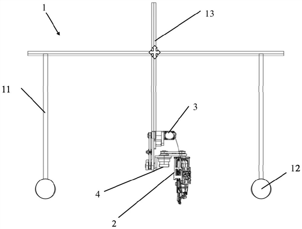
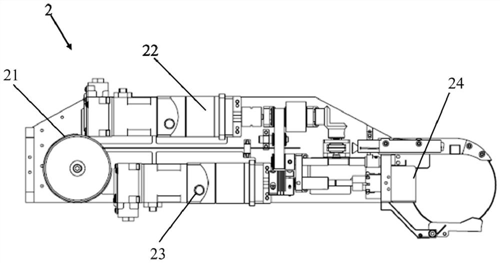

Image

  • Steel bar binding system and steel bar binding method
  • Steel bar binding system and steel bar binding method
  • Steel bar binding system and steel bar binding method

Examples


Embodiment Construction

[0055] In order for those skilled in the art to better understand the technical solutions of the present invention, the technical solutions of the present invention are further described below with reference to the accompanying drawings and through specific embodiments.

[0056] In the description of the present invention, it should be noted that the terms "upper", "lower", "left", "right", "vertical", "horizontal", "inner", "outer", etc. indicate the orientation or The positional relationship is based on the orientation or positional relationship shown in the accompanying drawings, or the orientation or positional relationship that is usually placed when the product is used, and is only for the convenience of describing the present invention, rather than indicating or implying that the device or element referred to must have The particular orientation, construction and operation in the particular orientation are therefore not to be construed as limitations of the invention. F...


PUM


Abstract

The invention relates to the technical field of construction machinery, in particular to a steel bar binding system and a steel bar binding method. The steel bar binding system provided by the present invention includes a BIM data import and scheduling module, a visual positioning module and an execution module. The BIM data import and scheduling module can store and publish the calibration coordinate data of the steel bar nodes in real time; the visual positioning module and the BIM data import and execution module The scheduling module is connected by communication, the visual positioning module can collect the actual coordinate data of the steel bar nodes, and obtain the compensation data according to the actual coordinate data and the calibration coordinate data, the BIM data import and scheduling module can optimize the calibration coordinate data according to the compensation data; the execution module and the BIM The data import and scheduling module are connected by communication, and the execution module can move according to the optimized calibration coordinate data and bind the steel bar nodes, realize automatic binding of steel bars, effectively release labor force, and improve the efficiency and quality of steel bar binding.

Description

technical field [0001] The invention relates to the technical field of construction machinery, in particular to a steel bar binding system and a steel bar binding method. Background technique [0002] In the construction industry, after laying steel bars, it is necessary to bundle the nodes of the staggered steel bars to ensure that the position of the steel bars remains unchanged and to ensure the structural strength of the steel bars. At present, there are two forms of bundling steel bars on the market: 1) Manual bundling with bundling hooks, low work efficiency, high labor intensity, and uncontrollable bundling quality; 2) Hand-held bundling guns for bundling, which are bulky, resulting in carrying and handling inconvenient. [0003] Therefore, there is an urgent need for a steel bar binding system to solve the above problems. SUMMARY OF THE INVENTION [0004] One object of the present invention is to provide a steel bar binding system, which can automatically bind st...

Claims


Application Information

Patent Timeline
Patent Type & Authority Patents(China)
IPC IPC(8): E04G21/12
CPCE04G21/12E04G21/123
Inventor 陈胜吕中广潘继文赵锐
Owner GUANGDONG BOZHILIN ROBOT CO LTD
Learn More