
Positioning limit type oil filter

An oil filter and filter element technology, which is applied in the fields of filtration and separation, mechanical equipment, engine components, etc., can solve problems such as unfavorable installation coordination and position limit, unfavorable automatic production requirements, insufficient support force of filter element components, etc., to achieve convenient Assembly, positioning function enhancement, the effect of reducing energy consumption

Inactive Publication Date: 2020-10-09
ZHEJIANG UNIVERSE FILTER
View PDF3 Cites 0 Cited by
  • Summary
  • Abstract
  • Description
  • Claims
  • Application Information

AI Technical Summary

Problems solved by technology

[0002] At present, the support spring in the bottom of the oil filter is in the form of a spiral. The support force for the bypass valve assembly and the filter element assembly is not enough, and the positioning effect is not obvious, and there may be a risk of shaking from side to side
And the contact surface between the check valve at the place between the screw-tight plate and the filter element assembly and the side of the filter element end cover of the filter element assembly is linear, which is not conducive to the installation and positioning between the two, and is even more unfavorable. Automated Production Requirements
The material of the filter element end cover of the filter element assembly is iron, which is artificially bonded on both sides with glue, the production efficiency is low, and it will cause environmental pollution after being discarded, which does not meet the environmental protection requirements

Method used


Image

  • Positioning limit type oil filter

Examples


Embodiment Construction

[0008] The present invention will be described in further detail below with reference to the drawings and embodiments.

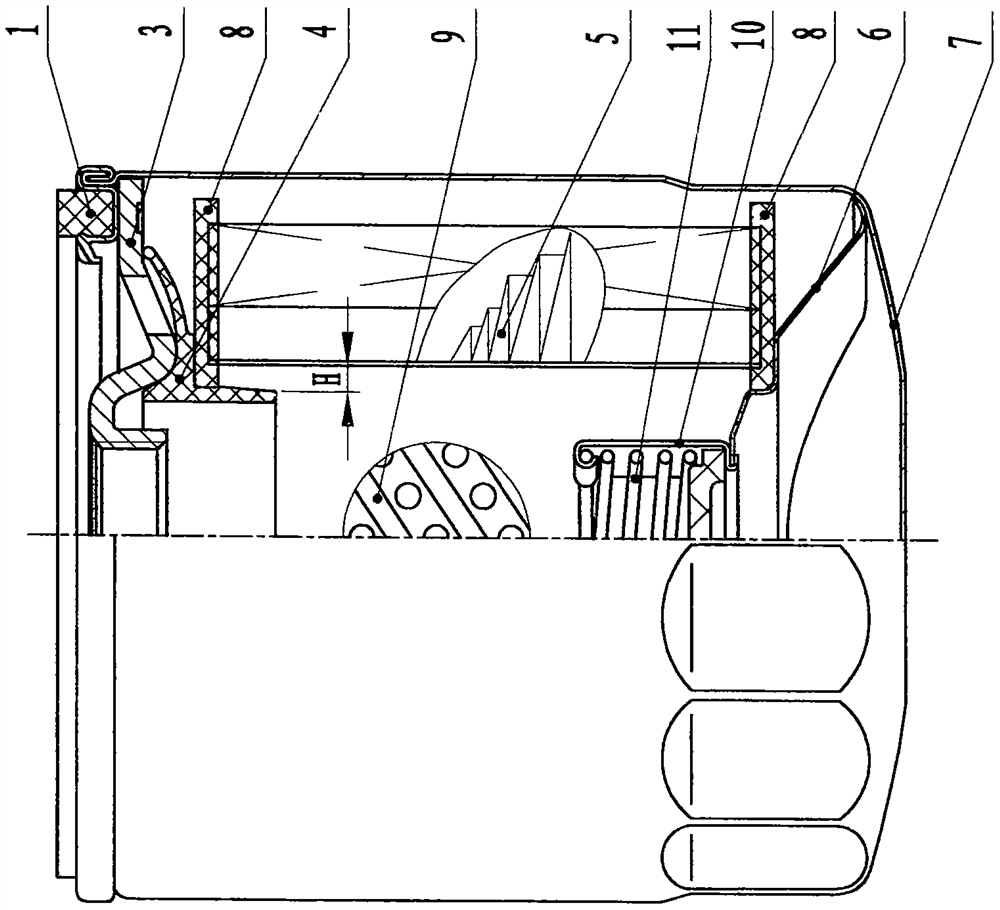
[0009] refer to figure 1 It can be seen that the position-limiting oil filter of the present invention includes a housing 7, a screw plate 3 (including a screw plate and a close plate), a filter element assembly, and a bypass valve assembly. The filter element assembly consists of a filter element end cover 8 (including an upper The filter element end cover and the lower filter element end cover), filter paper 5, and center pipe 9. The bypass valve assembly is composed of a bypass valve seat 10 (which already contains a bypass valve) and a bypass valve spring 11. The screw A check valve 4 is installed between the dense plate 3 and the (upper) filter element end cover 8 of the filter element assembly. The distance H between the side of the check valve and the filter paper gradually increases from top to bottom, which is beneficial to the assembly of the filt...


PUM


Abstract

The invention discloses a positioning limit type oil filter. The filter comprises a shell, a screw tight plate, a filter element assembly and a bypass valve assembly, wherein a check valve is installed between the screw tight plate and a filter element end cover of the filter element assembly, and the side part of the check valve and the side part of the filter element end cover are assembled in atapered structure; a wave spring piece is installed between a bypass valve seat of the bypass valve assembly and the inner bottom of the shell, and the wave spring piece is in supported contact withthe filter element end cover. The material of the filter element end cover is non-woven fabric. The tapered structure of the side part of the check valve provided by the invention can realize convenient assembly and limit functions when matched with the filter element end cover. The assembly of the wave spring piece supports the bypass valve assembly and the filter element assembly more closely, so that the positioning function is enhanced, and support is ensured to avoid shaking left and right. The filter element end cover of the filter element assembly is made of non-woven material, which isenergy-saving and environmentally friendly, reduces energy consumption, and improves production efficiency, thereby ensuring the quality of machine filter products and reducing labor costs.

Description

technical field [0001] The invention relates to a filtering facility, in particular to an engine oil filter. Background technique [0002] At present, the support spring in the bottom of the oil filter is in the form of a spiral. The support force for the bypass valve assembly and the filter element assembly is not enough, and the positioning effect is not obvious, and there may be a risk of shaking from side to side. And the contact surface between the check valve at the place between the screw-tight plate and the filter element assembly and the side of the filter element end cover of the filter element assembly is linear, which is not conducive to the installation and positioning between the two, and is even more unfavorable. Automated production needs. The material of the filter element end cover of the filter element assembly is iron, which is glued on both sides by manual glue, the production efficiency is low, and it will cause environmental pollution after being disc...

Claims


Application Information

Patent Timeline
Patent Type & Authority Applications(China)
IPC IPC(8): F16N39/06F16N23/00B01D39/14
CPCF16N39/06F16N23/00B01D39/14F16N2039/007
Inventor 叶南海王刁栋刘志千方辉韩伟伟刘万斌
Owner ZHEJIANG UNIVERSE FILTER
Learn More