Small optical imaging lens with high light flux

An optical imaging lens, Datongguang technology, applied in the lens field, can solve the problems of large overall size, inability to meet miniaturization requirements, and large sacrifice of illumination, so as to reduce the serious situation of pixel loss, control the optical transfer function well, and increase the The effect of recognition range

Pending Publication Date: 2020-10-09
XIAMEN LEADING OPTICS
View PDF0 Cites 0 Cited by
  • Summary
  • Abstract
  • Description
  • Claims
  • Application Information

AI Technical Summary

Problems solved by technology

[0003] In a system using TOF (time of flight) technology for 3D scanning, the performance of the TOF lens is critical, which will greatly affect the effect and reliability of 3D scanning
However, TOF lenses currently on the market still have many deficiencies, such as the relatively small aperture, which does not meet the ideal relative aperture required for the application; the overall size is large and the total length is long, which cannot meet the needs of

Method used


Image

  • Small optical imaging lens with high light flux
  • Small optical imaging lens with high light flux
  • Small optical imaging lens with high light flux

Examples


Embodiment 1

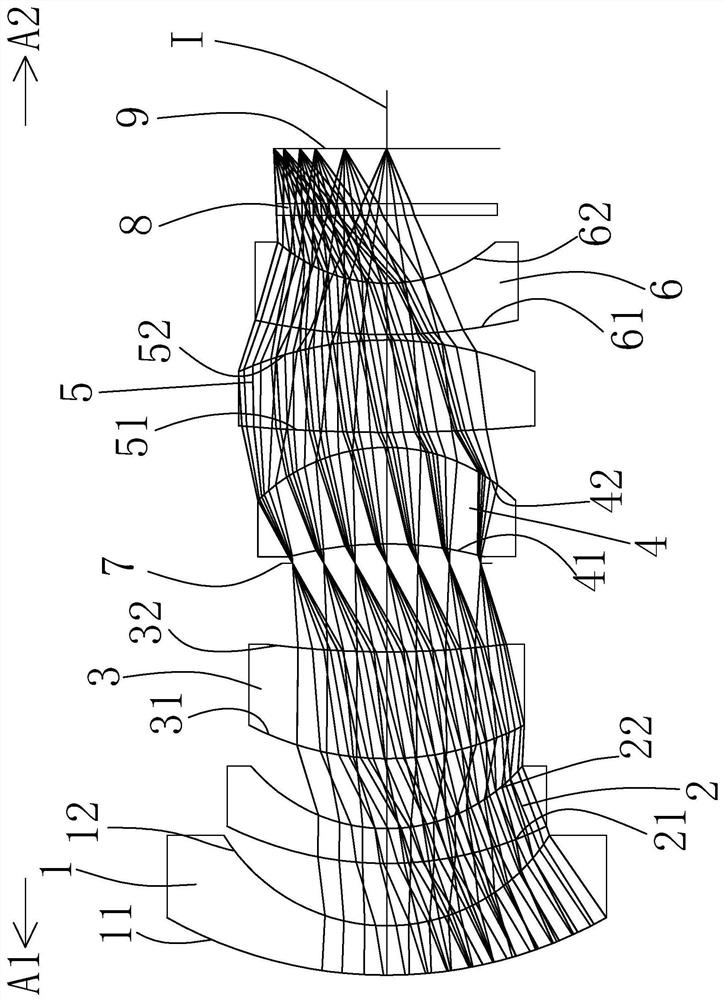
[0063] Such as figure 1 As shown in the figure, a small optical imaging lens with a wide range of light includes a first lens 1, a second lens 2, a third lens 3, a diaphragm 7, and a fourth lens in sequence along an optical axis I from the object side A1 to the image side A2 4. The fifth lens 5, the sixth lens 6, the optical filter 8 and the imaging surface 9; the first lens 1 to the sixth lens 6 each include an object side facing the object side A1 and allowing the imaging light to pass through, and an object side facing the image. Side A2 and let the imaging light pass through the image side.

[0064] The first lens 1 has a negative refractive power, the object side 11 of the first lens 1 is convex, and the image side 12 of the first lens 1 is concave.

[0065] The second lens 2 has a negative refractive power, the object side 21 of the second lens 2 is convex, and the image side 22 of the second lens 2 is concave.

[0066] The third lens 3 has a positive refractive power,...

Embodiment 2

[0093] Such as Figure 5 As can be seen, the concave-convex surface and refractive index of each lens in this embodiment and the first embodiment are the same, and only the optical parameters such as the radius of curvature of the lens surface and the thickness of the lens are different.

[0094] The detailed optical data of this specific embodiment are shown in Table 2-1.

[0095] Table 2-1 Detailed optical data of Example 2

[0096]

[0097] Please refer to the following table for the detailed data of the parameters of each aspheric surface in this specific embodiment:

[0098] surface 41 42 K= -7.285E+00 -3.174E-01 a 4 =

-1.392E-02 -4.136E-04 a 6 =

1.678E-03 -4.132E-04 a 8 =

-1.234E-03 -3.584E-05 a 10 =

7.326E-05 9.741E-06 a 12 =

6.722E-05 -1.349E-06 a 14 =

-1.335E-05 4.077E-09

[0099] Please refer to Table 5 for the values ​​of the relevant conditional expressions in this specific embodiment.

[0...

Embodiment 3

[0103] Such as Figure 9 As can be seen, the concave-convex surface and refractive index of each lens in this embodiment and the first embodiment are the same, and only the optical parameters such as the radius of curvature of the lens surface and the thickness of the lens are different.

[0104] The detailed optical data of this specific embodiment are shown in Table 3-1.

[0105] Table 3-1 Detailed optical data of Example 3

[0106]

[0107] Please refer to the following table for the detailed data of the parameters of each aspheric surface in this specific embodiment:

[0108]

[0109]

[0110] Please refer to Table 5 for the values ​​of the relevant conditional expressions in this specific embodiment.

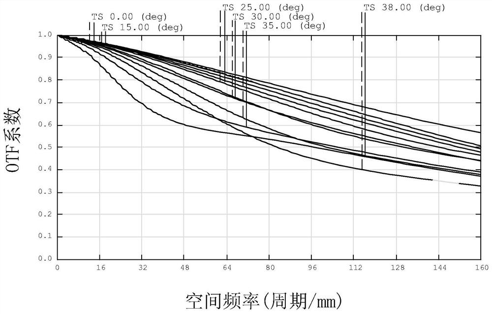
[0111] The MTF transfer function curve figure of this specific embodiment sees for details Figure 10 , it can be seen that the resolution is high, at 160lp / mm, the transfer function is still greater than 0.3, and the imaging quality is excellent, which can satisf...


PUM


Abstract

The invention relates to the technical field of lenses, and discloses a small optical imaging lens with high light flux. The small optical imaging lens with high light flux sequentially comprises a first lens, a second lens, a third lens, a fourth lens, a fifth lens and a sixth lens from an object side to an image side along an optical axis, wherein the first lens, the second lens and the sixth lens are all convex-concave lenses with a negative refractive index; the third lens has a positive refractive index, and the object side face of the third lens is a convex face; the fourth lens is a concave-convex lens with a positive refractive index; the fifth lens is a convex lens with a positive refractive index; and the object side face and the image side face of the third lens are aspheric faces or the object side face and the image side face of the fourth lens are aspheric faces. The small optical imaging lens of the invention has the advantages of high resolution, small distortion, goodimaging quality, large relative aperture, uniform relative illuminance and miniaturization.

Description

technical field [0001] The invention belongs to the field of lens technology, and in particular relates to a small optical imaging lens with large-scale light. Background technique [0002] With the continuous advancement of science and technology and the continuous development of society, optical imaging lenses have also developed rapidly in recent years. Optical imaging lenses are widely used in smart phones, tablet computers, video conferencing, vehicle monitoring, security monitoring, 3D scanning Therefore, the requirements for optical imaging lenses are also increasing. [0003] In a system using TOF (time of flight) technology for 3D scanning, the performance of the TOF lens is critical, which will greatly affect the effect and reliability of 3D scanning. However, TOF lenses currently on the market still have many deficiencies, such as the relatively small aperture, which does not meet the ideal relative aperture required for the application; the overall size is large...

Claims


Application Information

Patent Timeline
IPC IPC(8): G02B13/00G02B13/18
CPCG02B13/0015G02B13/0045
Inventor 刘青天上官秋和
Owner XIAMEN LEADING OPTICS
Why Eureka
Try Eureka