
Tightener for pin insulator

A technology of pin insulators and wire tensioners, applied in the direction of pin insulators, cable suspension devices, etc., can solve problems such as large randomness, cable overheating, low efficiency, etc., to save operating space, large contact area, and convenient rotation Effect

Pending Publication Date: 2020-10-09
GUANGZHOU PANYU CABLE WORKS
View PDF0 Cites 2 Cited by
  • Summary
  • Abstract
  • Description
  • Claims
  • Application Information

AI Technical Summary

Problems solved by technology

[0002] Pin insulators are usually used to fix high-voltage cables. When in use, the cables are tightly attached to the top or side slots of the pin insulators, and then the cables are bound and fixed with the pin insulators by winding wires. This method is inefficient and the binding method There is no uniform standard for the tightness of the binding and the tightness of the binding. The randomness is large, and it is easy to cause the wire to be not firmly fixed. It will become loose or even loose after long-term use. The wire is usually made of metal wires such as aluminum wires, which are directly wound on the cable sheath, which will cause the cable to loosen. Damage to the sheath may easily cause dangers such as overheating of the cable or even leakage and short circuit, and the insulated cable will be in direct contact with the metal wire, resulting in hidden dangers of leakage

Method used


Image

  • Tightener for pin insulator
  • Tightener for pin insulator
  • Tightener for pin insulator

Examples


Embodiment Construction

[0024] In order to make the object, technical solution and advantages of the present invention clearer, the present invention will be further described in detail below in conjunction with the accompanying drawings and embodiments. It should be understood that the specific embodiments described here are only used to explain the present invention, not to limit the present invention.

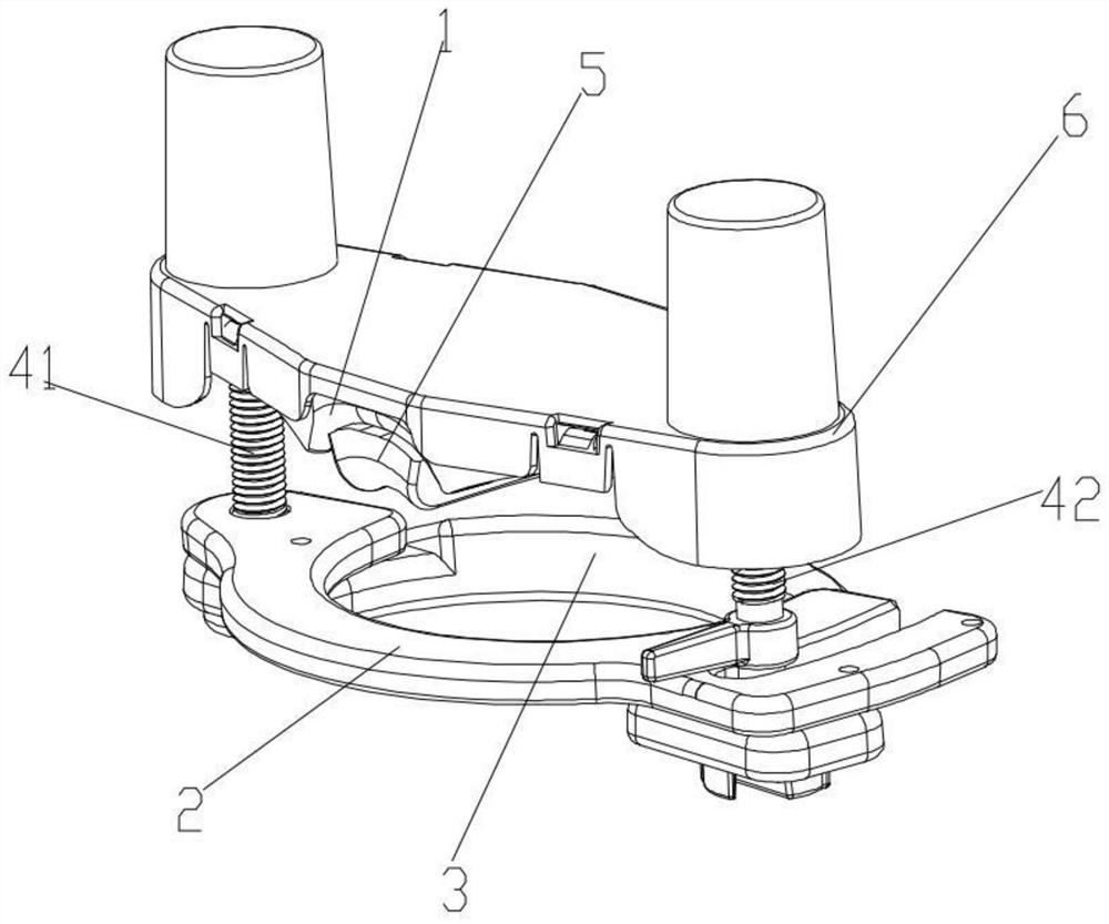
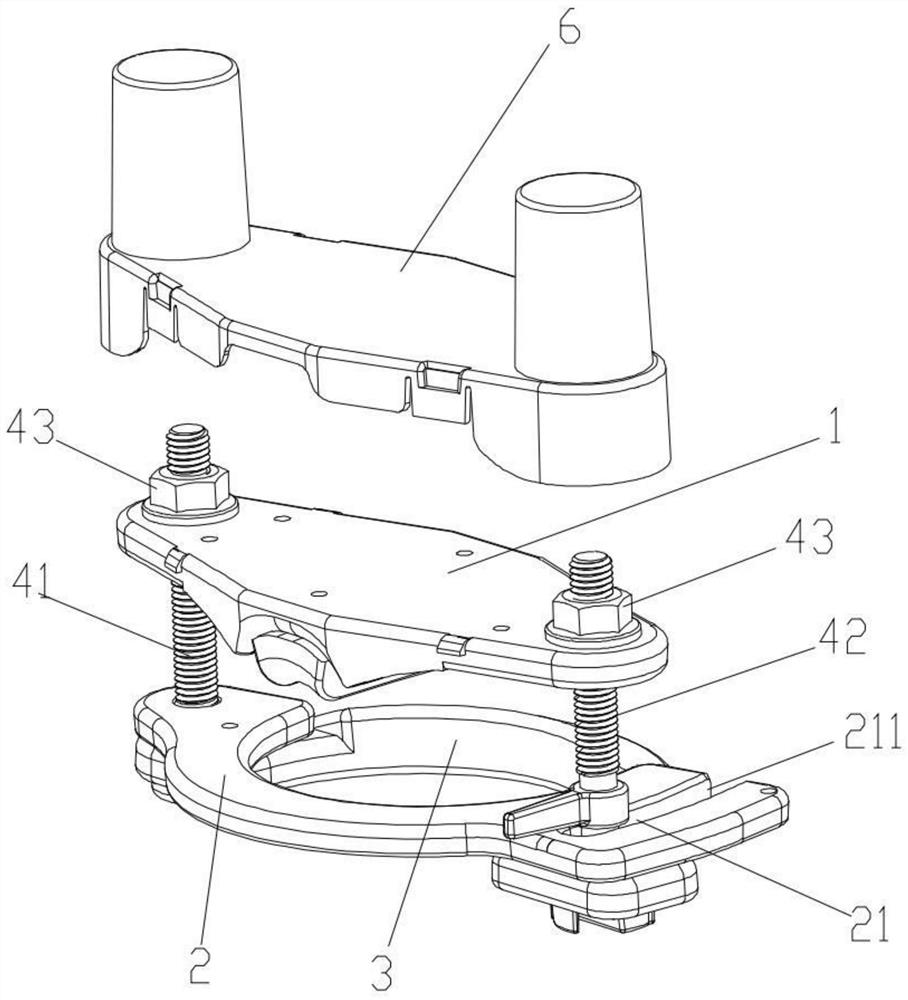
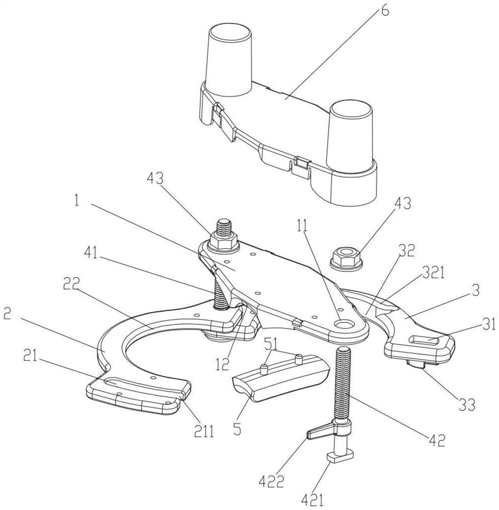
[0025] Such as Figure 1-5 As shown, a wire tightener for pin insulators includes a pressing plate 1, an upper splint 2 and a lower splint 3 arranged in sequence, and one end of the pressing plate 1, the upper splint 2 and the lower splint 3 is hinged by a first screw 41, The other end is respectively provided with the first through hole 11, the second through hole 21 and the third through hole 31 for the second screw rod 42 to pass through, the pressing plate 1 can reciprocate along the first screw rod 41 and the second screw rod 42, and the upper splint 2 and the middle part of the lower splint ...


PUM


Abstract

The invention relates to the field of cable installation, in particular to a tightener for a pin insulator. The tightener comprises a pressing plate, an upper splint and a lower splint, wherein one ends of the upper splint and lower splint are hinged through a first screw rod; a first through hole, a second through hole and a third through hole for a second screw rod to penetrate through are formed in the other end of the upper splint and lower splint; the pressing plate can reciprocate along the first screw rod and the second screw rod; the upper splint and lower splint are respectively provided with a first arc-shaped structure and a second arc-shaped structure which are opposite to match and form a clamping ring used for clamping and embedding an annular side groove of the pin insulator, the pressing plate is located above the pin insulator, the first screw rod and the second screw rod are each provided with a corresponding locking nut, and the pressing plate can move towards the upper splint and lower splint by screwing the locking nuts so that a cable can be pressed on a top groove of the pin insulator. The tightener for the pin insulator can replace a wire binding mode to fixa cable on the pin insulator, and is simple in structure, convenient and fast to use and firm in fixation.

Description

technical field [0001] The invention relates to the field of cable installation, in particular to a wire tightener for pin insulators. Background technique [0002] Pin insulators are usually used to fix high-voltage cables. When in use, the cables are tightly attached to the top or side slots of the pin insulators, and then the cables are bound and fixed with the pin insulators by winding wires. This method is inefficient and the binding method There is no uniform standard for the tightness of the binding and the tightness of the binding. The randomness is large, and it is easy to cause the wire to be not firmly fixed. It will become loose or even loose after long-term use. The wire is usually made of metal wires such as aluminum wires, which are directly wound on the cable sheath, which will cause the cable to loosen. If the sheath is damaged, it is easy to cause dangers such as overheating of the cable or even leakage and short circuit, and the insulated cable will direct...

Claims


Application Information

Patent Timeline
IPC IPC(8): H02G7/05H01B17/22
CPCH01B17/22H02G7/05
Inventor 胡超强黄应敏邹科敏尤占山邵源鹏高伟光许翠珊冯泽华徐秋燕王骞能胡玉莹陈雪儿刘金勇陈匡迪郝燕冯家杰
Owner GUANGZHOU PANYU CABLE WORKS
Learn More