Self-dust-falling overheat protection device for electromechanical equipment

A technology for electromechanical equipment and overheating protection, which is applied in the construction of electrical equipment components, modification through conduction heat transfer, electrical components, etc., can solve problems such as poor heat dissipation, achieve stable operation, improve cooling effect, and good ventilation and heat exchange effect of effect

Inactive Publication Date: 2020-10-09
符必容
View PDF10 Cites 4 Cited by
  • Summary
  • Abstract
  • Description
  • Claims
  • Application Information

AI Technical Summary

Problems solved by technology

[0005] The purpose of the present invention is to solve the problem of poor heat dissipation effect, and provide a self-dust-reducing overheating protection device for electromechanical equipment with good heat dissipation effect

Method used


Image

  • Self-dust-falling overheat protection device for electromechanical equipment
  • Self-dust-falling overheat protection device for electromechanical equipment

Examples


Embodiment 1

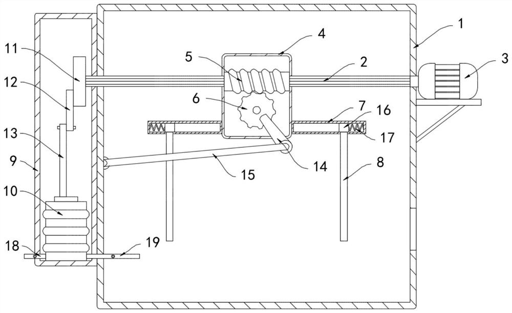
[0021] Such as figure 1 As shown, a self-dusting overheating protection device for electromechanical equipment includes a box body 1, a horizontally arranged slide bar 2 is rotatably connected to the inner side wall of the box body 1, and a drive motor 3 is installed on the side wall of the box body 1 to drive The output shaft of the motor 3 extends into the box body 1 and is coaxially fixed with the slide rod 2. The outside of the slide rod 2 is slidably sleeved with a housing 4. The inner wall of the housing 4 is connected with a worm 5 for rotation. The inner axis of the worm 5 is extended. The direction is provided with a circular cavity, the worm 5 is slidably socketed outside the slide rod 2, and the worm wheel 6 is connected to the housing 4 in rotation, the worm wheel 6 is meshed with the worm 5, and the worm wheel 6 is connected to the inner wall of the box body 1 through a transmission mechanism. The transmission mechanism includes a connecting rod 14 fixedly connect...

Embodiment 2

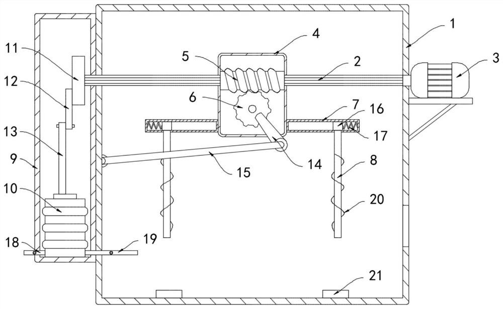
[0028] Such as figure 2 As shown, the difference between the present embodiment and the first embodiment lies in that: the heat sink 8 is wound with a conductive coil 20 , and the inner bottom surface of the box body 1 is fixed with a permanent magnet 21 .

[0029] In this embodiment, the heat sink 8 drives the conductive coil 20 to reciprocate in translation. According to the principle of electromagnetic induction, when the magnetic flux in the closed coil changes, an induced current is generated in the closed coil, and the conductive coil 20 is permanently in the process of reciprocating movement. The magnetic flux of the magnetic block 21 in the conductive coil 20 changes, and an induced current is generated in the conductive coil 20. When the heat sink 8 drives the conductive coil 20 to contact the electromechanical equipment, the dust attached to the surface of the electromechanical equipment can be sucked away, so as to avoid dust covering and affecting other components....


PUM


Abstract

The invention belongs to the field of electromechanical equipment and particularly relates to a self-dust-falling overheat protection device for electromechanical equipment. The protection device comprises a box body, wherein the inner side wall of the box body is rotationally connected with a horizontally-arranged sliding rod; a driving motor is mounted on the side wall of the box body; an outputshaft of the driving motor extends into the box body and is coaxially fixed with the sliding rod; the sliding rod is sleeved with a shell in a sliding mode; the inner side wall of the shell is rotationally connected with a worm; a circular cavity is formed in the worm in a delay axis direction; and the worm is slidably sleeved with the sliding rod; a worm wheel is arranged in and rotatably connected with the shell; the worm wheel is connected with the worm in a meshed mode; the worm wheel is connected with the inner side wall of the box body through a transmission mechanism; sliding grooves are fixedly formed in the side walls of the two sides of the shell; and cooling fins are slidably connected to the lower ends of the sliding grooves. Electromechanical equipment can be cooled through the cooling fins and telescopic air bags at the same time, operation is stable and efficient, and the possibility of overheating damage to the electromechanical equipment is greatly reduced.

Description

technical field [0001] The invention belongs to the field of electromechanical equipment, and in particular relates to a self-dust-reducing overheat protection device for electromechanical equipment. Background technique [0002] With the development of science and technology, traditional mechanical equipment has entered a new stage of the combination of mechanical and electrical, and its application range has been continuously expanded. People have more and more demands for electromechanical equipment in production and life. Greatly improved production efficiency and reduced labor intensity. [0003] When the existing electromechanical equipment works for a long time, a large amount of heat is generated inside and it is difficult to dissipate in time, which often causes the problem of overheating of the equipment, greatly reduces the working efficiency of the electromechanical equipment, and is prone to failure, resulting in a reduction in its service life. Most of the ele...

Claims


Application Information

Patent Timeline
Patent Type & Authority Applications(China)
IPC IPC(8): H05K7/20B08B6/00
CPCB08B6/00H05K7/20136H05K7/2039
Inventor 符必容
Owner 符必容
Why Eureka
Try Eureka