Welding-free air-cooled heat dissipation light emitting diode lamp

A light-emitting diode lamp, welding-free technology, which is applied to semiconductor devices of light-emitting elements, cooling/heating devices of lighting devices, light sources, etc., can solve the problems of manufacturing trouble, welding temperature false welding, overheating of lamp beads, etc., and save materials. and working hours, rapid heat dissipation and cooling, and the effect of accelerated cooling and heat dissipation

Inactive Publication Date: 2018-12-18
江西联同电子科技有限公司
View PDF5 Cites 0 Cited by
  • Summary
  • Abstract
  • Description
  • Claims
  • Application Information

AI Technical Summary

Problems solved by technology

However, since the existing LED lamps are all combined with light-emitting diodes, there are the following problems in the existing LED lamps: First, when welding in the production line, due to the large heat absorption of the aluminum substrate and the small heat absorption of the chip electrodes, the welding temperature It is difficult for ordinary people to grasp it properly. If the soldering temperature is too high, it will easily cause damage to the chip. If the soldering temperature is too low, it will easily cause false soldering and false soldering, which will cause poor contact and open circuit failure in the circuit. And burn out, the outer surface of the aluminum plate must be equipped with a radiator, and the joint between the existing radiator and the aluminum substrate is not tight and there is a gap, which will cause the heat emitted by the lamp beads to be transferred to the radiator. However, the lamp bead is overheated, and at the same time, the heat dissipation effect of the existing radiator is not very good, and the operating temperature of the chip is too high, which affects the luminous brightness and service life of the chip, and the radiator is relatively large in size, takes up space, troublesome to manufacture, and expensive to manufacture. also high

Method used


Image

  • Welding-free air-cooled heat dissipation light emitting diode lamp
  • Welding-free air-cooled heat dissipation light emitting diode lamp
  • Welding-free air-cooled heat dissipation light emitting diode lamp

Examples


Embodiment Construction

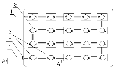
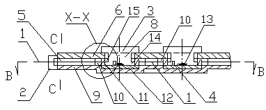
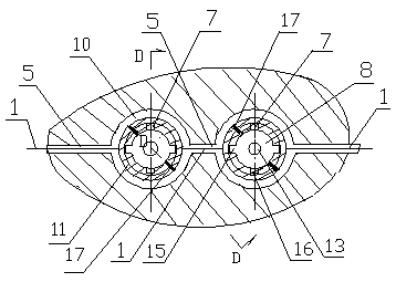
[0016] In the figure, the solder-free air-cooled heat dissipation light-emitting diode lamp is rectangular, and it consists of five rows, and each row is composed of five chips 3 (lamp beads) connected in series with conductive wire 1. The solder-free air-cooled heat dissipation emits light The diode lamp includes an upper substrate 6 and a lower substrate 9 which is sealed and fixed (sealed with glue or screws) to the upper substrate, grooves are arranged at intervals on the lower substrate, and grooves are arranged in the grooves to be flush with the upper surface of the lower substrate. The thermally conductive adhesive layer 12, the conductive ring 11 is fixedly arranged on the thermally conductive adhesive layer, and the insulating adhesive layer 17 is used in the middle of the conductive ring ( image 3 The position of the black line in the middle) is separated, and the insulating adhesive layer is separated by 45° to separate the conductive ring. The bottom surface of th...


PUM


Abstract

The invention discloses a welding-free air-cooled heat dissipation light emitting diode lamp. The welding-free air-cooled heat dissipation light emitting diode lamp comprises an upper base plate and alower base plate which is connected with the upper base plate in a seal fixed manner. Heat-conducting rubber layers are arranged on the lower base plate at intervals and provided with conducting rings, the middles of the conducting rings are separated by insulating rubber layers, and an annular limiting slot and axial open slots are formed in the lower end of each conducting ring. Elastic layersare arranged in the middles of the heat-conducting rubber layers. Conducting cylinders are arranged in the conducting rings. The lower ends of the conducting rings are symmetrically connected with cathode fixture blocks and anode fixture blocks respectively. The upper base plate is provided with ventilating circuits and ventilating holes arranged linearly, the conducting rings are surrounded by the ventilating circuits, the ventilating circuits communicate with the ventilating holes, conducting wires connected with the conducting rings are arranged in the ventilating holes, a miniature motor is arranged at the outer ports of the ventilating holes, and the miniature motor is connected with thermocouples arranged in the conducting cylinders. The heat dissipation effect of chips is improved,radiator materials and manufacturing labor time are saved, the size of the lamp is reduced, the weight of the lamp is lowered, and the manufacturing cost of the lamp is reduced.

Description

technical field [0001] The invention relates to a light-emitting diode (LED) lamp, in particular to a light-weight light-emitting diode lamp free from welding, ventilation, forced cooling and heat dissipation. Background technique [0002] With the rapid development of the economy and the continuous improvement of people's living standards, electricity consumption has increased rapidly and become more and more tense. As we all know, compared with existing incandescent lamps and fluorescent lamps, LED lamps made of light-emitting diodes have the advantages of high luminous intensity, long life and low power consumption. LED lamps have been widely used as lighting lamps, landscape lamps, advertising lamps, Wall washers and ceiling lights, etc., can be applied to real electricity, as well as solar and wind power generation. Therefore, the comprehensive promotion of the use of LED lights has the advantages of improving the use effect and saving a lot of electric energy. However...

Claims


Application Information

Patent Timeline
IPC IPC(8): F21V19/00F21V29/83F21V29/61F21V29/67F21Y115/10
Inventor 陆金发
Owner 江西联同电子科技有限公司
Why Eureka
Try Eureka