Three-axis milling mechanism for machining T-shaped slot of vertical lathe rotary table

A technology of rotary table and vertical lathe, which is applied in the field of machine tools, can solve the problems of high manufacturing cost, large diameter of vertical lathe rotary table, time-consuming and labor-intensive problems, and achieve the effect of reducing the number of clamping times, reducing man-hours, and reducing manufacturing costs

Pending Publication Date: 2020-10-13
QIQIHAR JINGGONG WEIYE MACHINE TOOLS CO LTD
View PDF0 Cites 0 Cited by
  • Summary
  • Abstract
  • Description
  • Claims
  • Application Information

AI Technical Summary

Problems solved by technology

[0003] In order to solve the problem that the existing vertical lathe rotary table has a large diameter and adopts gantry milling, which requires transposition clamping, time-consuming and laborious, and high manufacturing costs, the present invention provides a T-shaped vertical lathe rotary table. Three-axis Milling Mechanism for Slots

Method used


Image

  • Three-axis milling mechanism for machining T-shaped slot of vertical lathe rotary table
  • Three-axis milling mechanism for machining T-shaped slot of vertical lathe rotary table
  • Three-axis milling mechanism for machining T-shaped slot of vertical lathe rotary table

Examples


Embodiment 1

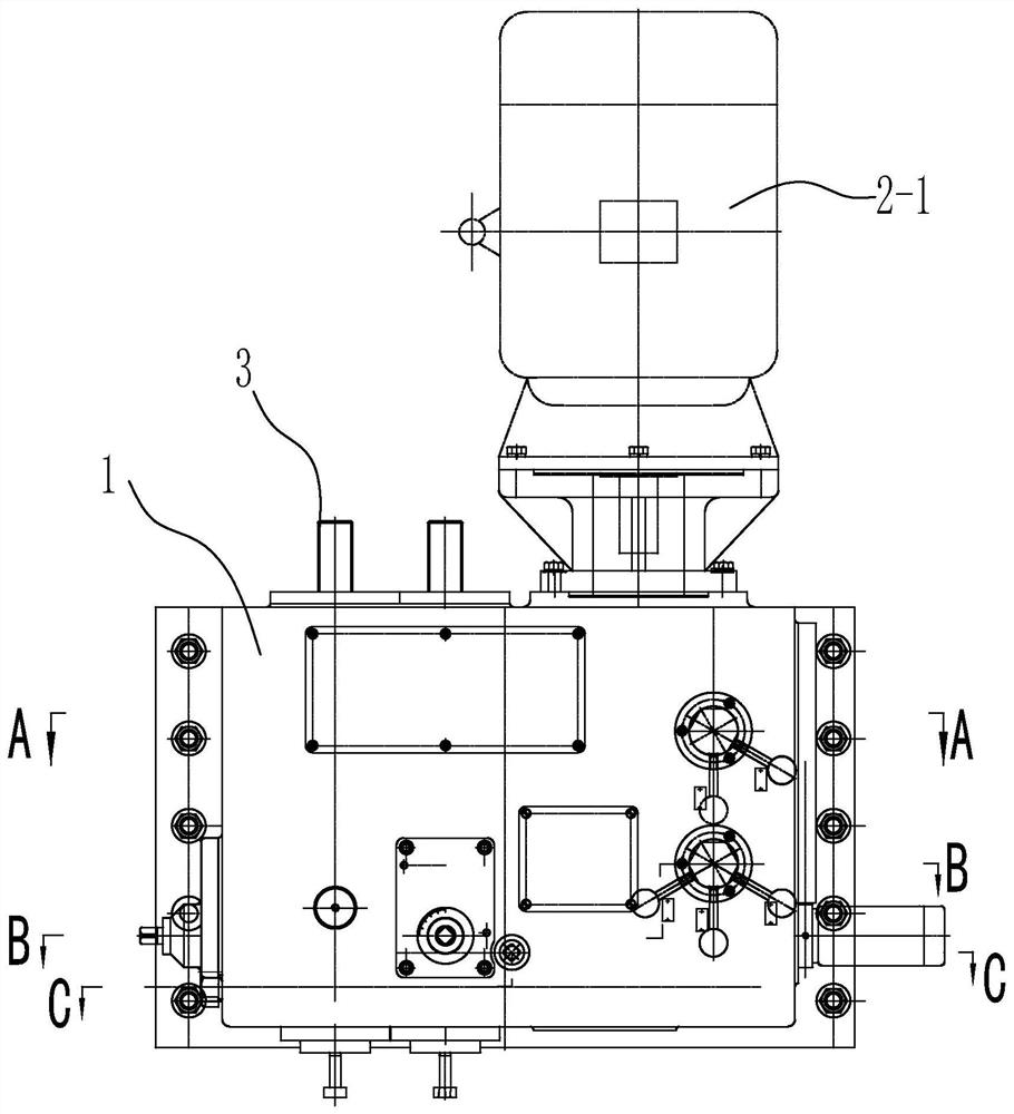
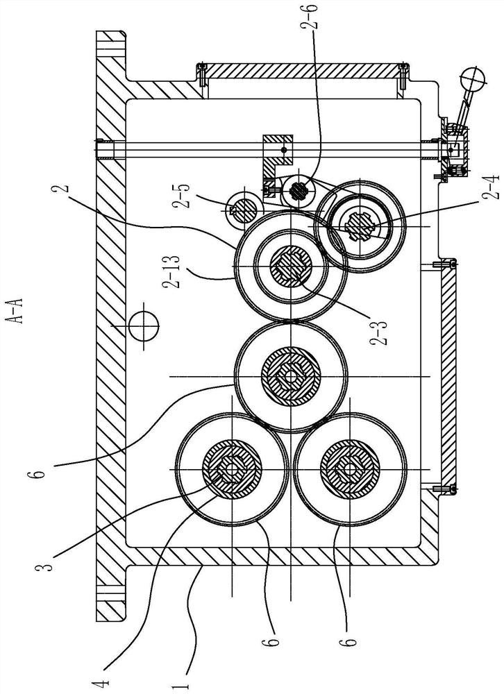
[0029] Embodiment 1: as Figure 2-Figure 4 As shown, this embodiment relates to a three-axis milling mechanism for machining T-shaped slots of a vertical lathe rotary table, including a spindle box 1, a speed-regulating drive mechanism 2, three spindles 3 and three spindle sleeves 4;

[0030] The main shaft box 1 is provided with three parallel spindle sleeves 4, and each main shaft sleeve 4 is provided with a main shaft 5 for rotation, and each main shaft 5 is provided with a gear 6, and each gear 6 passes through each main shaft 5. The gear 6 on one of the main shafts 5 meshes with the gears 6 on the other two main shafts 5 , and the gear 6 on one of the three main shafts 5 is driven by the speed-adjusting drive mechanism 2 .

[0031] Specifically, such as figure 2 , image 3 , Figure 4 and Image 6 As shown, the speed regulating drive mechanism 2 includes a motor 2-1, IV shaft 2-2, IVa shaft 2-3, V shaft 2-4, VI ​​shaft 2-5 and two shift forks 2-7;

[0032] IV axis 2...


PUM


Abstract

The invention provides a three-axis milling mechanism for machining a T-shaped slot of the vertical lathe rotary table, and belongs to the technical field of machine tools. The three-axis milling mechanism for machining the T-shaped slot of the vertical lathe rotary table aims to solve the problems that the indexing cannot be achieved by a conventional indexing plate due to the fact that an existing vertical lathe rotary table has a large diameter, and time and labor are wasted and the manufacturing cost is relatively high due to the fact a planer type milling machine is used for machining, and the position needs to be changed for clamping. The three-axis milling mechanism for machining the T-shaped slot of the vertical lathe rotary table includes a main shaft box, a speed-regulating drivemechanism, three main shafts and three main shaft sleeves; the main shaft box is provided with the three parallelly arranged main shaft sleeves, and the main shafts are rotatably arranged in each main shaft sleeve; and gears are arranged on the main shafts, each gear is connected with each main shaft through keys, the gear on one of the main shafts meshes with the gears on the other two main shafts, and the gear on one of the three main shafts is driven by the speed-regulating drive mechanism. The three-axis milling mechanism for machining the T-shaped slot of the vertical lathe rotary tableis suitable for a special machine tool for machining the rotary table.

Description

technical field [0001] The invention relates to a milling mechanism for a special machine tool, which belongs to the technical field of machine tools. Background technique [0002] The vertical lathe rotary table is usually used to process workpieces with relatively large diameters, such as figure 1 As shown, the diameter of the workbench itself is 4.5m, and there are four sets of T-shaped slots distributed at 90° on the vertical lathe workbench, and each set of T-shaped slots has two parallel to each other. The processing of the T-shaped slot requires gantry milling, which requires multiple transposition and clamping, which is time-consuming and labor-intensive, resulting in high manufacturing costs. Contents of the invention [0003] In order to solve the problem that the existing vertical lathe rotary table has a large diameter and adopts gantry milling, which requires transposition clamping, time-consuming and laborious, and high manufacturing costs, the present inven...

Claims


Application Information

Patent Timeline
Patent Type & Authority Applications(China)
IPC IPC(8): B23C3/34B23C1/04
CPCB23C1/04B23C3/34
Inventor 张文广李志博何伟光刘伟
Owner QIQIHAR JINGGONG WEIYE MACHINE TOOLS CO LTD
Why Eureka
Try Eureka