Guide rail for maglev train
A technology of magnetic levitation trains and guide rails, which is applied in the direction of tracks, roads, buildings, etc., can solve the problems of limited effect of magnetic field increase, and achieve the effects of improving ride comfort, increasing load capacity, and increasing effective area
- Summary
- Abstract
- Description
- Claims
- Application Information
AI Technical Summary
Problems solved by technology
Method used
Image
Examples
Embodiment 1
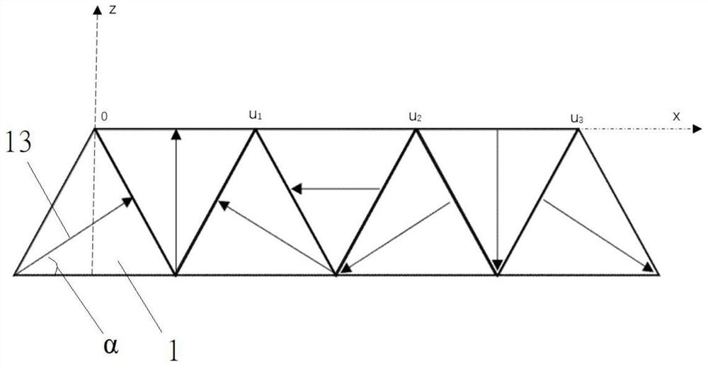
[0050] see figure 2 , in the permanent magnet rail structure, the number Z of polygonal magnetic steel blocks satisfies Z=4*n+3, (n∈N * ), in this embodiment, the magnetic steel block adopts an equilateral triangle structure, and a total of seven blocks (that is, the case of n=1) are arranged and spliced in sequence to form an isosceles trapezoidal structure
[0051] Further, to promote the magnetization direction of each polygonal magnetic steel of the guide rail involved in this patent, it should first be stipulated that the direction parallel to the upper edge of the guide rail is the horizontal direction, facing the guide rail section, the direction of the vector perpendicular to the horizontal direction and pointing to the right is positive Direction, magnetization angle θ angle is the angle after changing with the horizontal direction in the counterclockwise positive direction, and the local coordinate system of the above-mentioned permanent magnet guide rail is a rig...
Embodiment 2
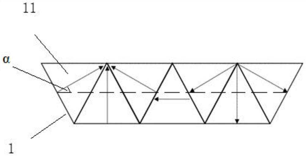
[0067] see image 3 In the middle, it is also a permanent magnet array composed of 7 equilateral triangles arranged in a single row. The coordinates of the right-handed system are used. The magnetization direction of the first magnet on the left is to rotate 30° counterclockwise to the right along the horizontal direction, and then start from the first magnet. Starting with the magnets, first lay out six magnets, turn the magnetization direction of each magnet to the right in turn 60°counterclockwise than the magnetization direction of the previous magnet, and then lay a charging magnet in the middle of the six magnets. The triangular magnet whose magnetic direction is horizontal to the left, compared with Example 1, the main difference is that the arrangement of the magnets is different. The magnetization direction of the magnet in Example 2 makes the adjacent magnets along the The vertex angles of the magnetization direction form a convergence. In actual production, the same...
Embodiment 3
[0069] In the array structure, the number Z of polygonal magnetic steel blocks satisfies Z=4*n+3, (n∈N * ) where the 4th*n, (n∈N * ) The polygonal permanent magnet can be replaced by soft magnetic materials of the same structure. Therefore, for the permanent magnet array of embodiment 2, if one of the magnetic steels is replaced with a soft magnetic body, different effects can be produced. Such as Figure 4 As shown, the gray part in the figure is an alternative soft magnetic material, and its internal magnetic flux direction is generally close to the horizontal direction. Adding soft magnetic material will greatly reduce the magnetic field strength of the left and right magnetic poles, which will reduce the convergence of the same magnetic poles cause demagnetization problems. However, since the permanent magnet is replaced by a soft magnetic material, the magnetic field intensity on its surface will be significantly reduced. Compared with the arrangement in Example 1 of t...
PUM
 Abstract
Description
Claims
Application Information
 - R&D
- Intellectual Property
- Life Sciences
- Materials
- Tech Scout
- Unparalleled Data Quality
- Higher Quality Content
- 60% Fewer Hallucinations
Browse by: Latest US Patents, China's latest patents, Technical Efficacy Thesaurus, Application Domain, Technology Topic, Popular Technical Reports.
© 2025 PatSnap. All rights reserved.Legal|Privacy policy|Modern Slavery Act Transparency Statement|Sitemap|About US| Contact US: help@patsnap.com


