Permanent magnet array

A technology of permanent magnets and arrays, applied in the direction of magnets, magnetic objects, permanent magnets, etc., can solve the problems of limited effect of magnetic field increase, increase of magnetic field strength above the track, etc.

Active Publication Date: 2020-10-20
苏州英磁新能源科技有限公司
View PDF14 Cites 4 Cited by
  • Summary
  • Abstract
  • Description
  • Claims
  • Application Information

AI Technical Summary

Problems solved by technology

The permanent magnet guide rails used for the suspension of superconducting trains described in these patents are all specific rectangular magnetic steels, which are arranged along the specific magnetization directions in the horiz

Method used


Image

  • Permanent magnet array
  • Permanent magnet array
  • Permanent magnet array

Examples


Embodiment 1

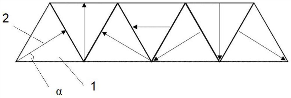
[0033] The magnetic steel block adopts a regular triangular structure, and a total of seven blocks are arranged and spliced ​​in sequence to form an isosceles trapezoidal structure with a base angle of 60 degrees. To promote the magnetization direction of each piece of magnet steel in the magnet steel array involved in this patent, it should first be stipulated that the direction parallel to the edge line above the array is the horizontal direction, facing the cross section of the array, the direction of the vector perpendicular to the horizontal direction and pointing to the right is positive Direction, magnetization angle θ angle is the angle after the horizontal direction changes in the counterclockwise positive direction, and the local coordinate system of the above-mentioned permanent magnet array is a right-handed system. In this embodiment, in the array structure composed of seven equilateral triangle magnets, the magnetization direction of the first magnet on the left i...

Embodiment 2

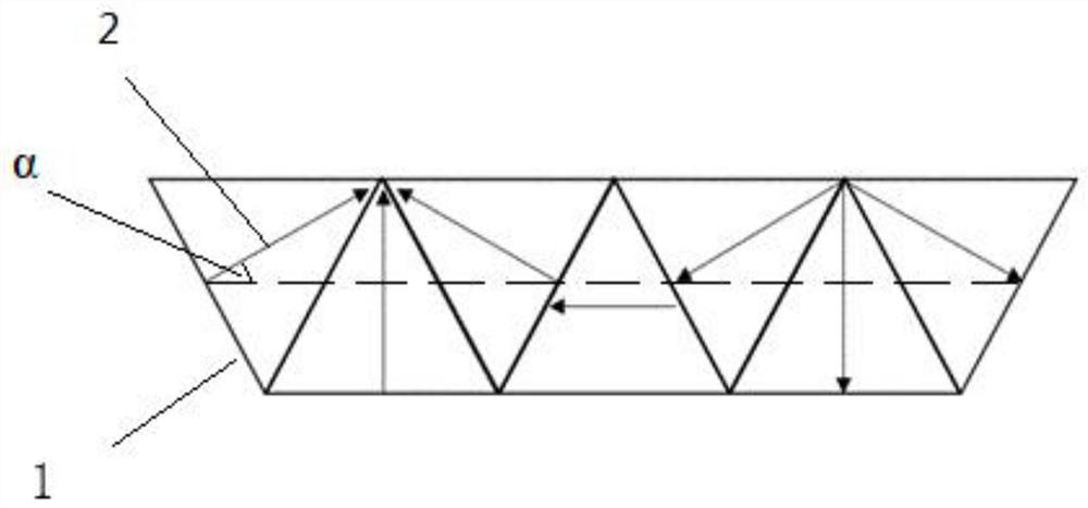
[0040] A permanent magnet array of the present invention can be applied in a permanent magnet guide rail, and includes an array structure composed of several equilateral triangular magnets 1 of the same size arranged in sequence, and the magnetization directions of adjacent equilateral triangular magnets are different, so that the magnetic field Convergence, the number of magnetic steel blocks Z, satisfying Z=4*n+3, (n∈N * ). In this implementation case, when chamfering is considered, such as Figure 6 shown. In implementation case 2, the number of magnetic steel blocks satisfies the above formula, that is, the case where n=1.

[0041] Specifically, the sequential arrangement here means that the corresponding sides of the adjacent equilateral triangle magnets are closely attached to each other, and the top corners of each equilateral triangle are provided with chamfers, and the chamfers are ≥0.5mm*45°. see Figure 4 Among them, the preferred value of this embodiment is 0.5...

Embodiment 3

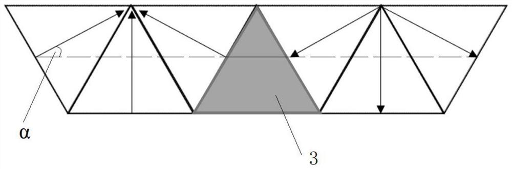
[0044] In this embodiment, the number Z of magnetic steel blocks satisfies Z=4*n+3, (n∈N * ) in the case of n=1, that is, there is a topological array structure composed of 7 pieces of magnetic steel. In this implementation case, when there is chamfering, it is as follows Figure 7 As shown, it is stipulated that the bottom edge of the first triangular magnetic steel block from left to right is the horizontal direction, and the included angle between the magnetization direction of the first triangular magnetic steel and the horizontal direction to the right is, then The [] here indicates the value range of α. Implementation Case 3 satisfies the situation that the magnetization angle of the first piece of magnetic steel is α=60°, and the magnetization direction of each subsequent permanent magnet satisfies the detailed formula. The entire permanent magnet array is composed The angle θ(θ∈R) between the magnetization direction of each magnet and the horizontal right direction, t...


PUM


Abstract

The invention discloses a permanent magnet array, which is formed by sequentially arranging a plurality of pieces of regular triangle magnetic steel with the same size. The magnetizing directions of the adjacent pieces of regular triangle magnetic steel are different, so that magnetic fields are unilaterally converged; the number of the magnetic steel is Z, and Z is equal to 4*n+3, and n belongs to N*. During use, in the permanent magnet array, the magnetizing directions of the adjacent 2 to 4 pieces of magnetic steel converge, magnetic lines of force are superposed through local N-pole or S-pole magnetic field convergence, the unilateral magnetic flux density of the permanent magnet array is increased, the effect of enhancing the unilateral magnetic field on the surface of the guide railis achieved, and the magnetic field intensity above the array and the effective area of the magnetic field intensity are increased.

Description

technical field [0001] The present invention mainly relates to the technical field of permanent magnets, in particular to an array of permanent magnets, in particular to an array of permutations and combinations of permanent magnets with different magnetization directions. Background technique [0002] The existing permanent magnet array usually adopts several square permanent magnets arranged in sequence to generate a certain magnetic field, which can be applied in various occasions. [0003] For example, the permanent magnet array used in the traditional superconducting levitation model only arranges the permanent magnets in an N-S manner to form a stable magnetic field and achieve the purpose of suspending the superconducting material. In the ordinary scheme, in order to enhance the magnetic field above the permanent magnet track, Usually, rare earth permanent magnets are used as permanent magnets. Even so, the surface magnetic field intensity provided by the orbits is ve...

Claims


Application Information

Patent Timeline
IPC IPC(8): H01F7/02
CPCH01F7/0273
Inventor 裴瑞琳高凌宇张航
Owner 苏州英磁新能源科技有限公司
Why Eureka
Try Eureka