A permanent magnet array
A permanent magnet and array technology, applied in the direction of magnets, permanent magnets, magnetic objects, etc., can solve the problem of limited effect of magnetic field increase, increase the magnetic field strength above the track, etc. Wide range of effects
- Summary
- Abstract
- Description
- Claims
- Application Information
AI Technical Summary
Problems solved by technology
Method used
Image
Examples
Embodiment 1
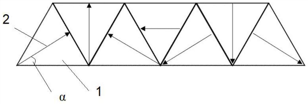
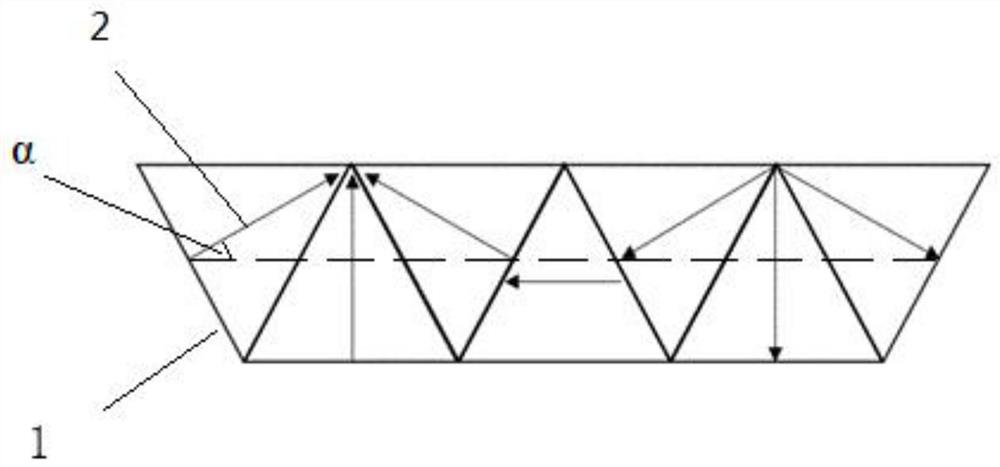
[0033] The magnetic steel block adopts a regular triangle structure, and a total of seven blocks are arranged in sequence to form an isosceles trapezoid structure with a base angle of 60 degrees. To generalize the magnetization direction of each magnetic steel in the magnetic steel array involved in this patent, the direction parallel to the upper edge of the array should be defined as the horizontal direction, and the vector direction facing the array section, perpendicular to the horizontal direction and pointing to the right is positive. direction, the magnetization angle θ is the angle that is changed from the horizontal direction in the counterclockwise positive direction, and the local coordinate system of the permanent magnet array is a right-handed system. In this embodiment, in the array structure composed of seven equilateral triangular magnet steels, the magnetization direction of the first magnet steel on the left is to rotate 30° counterclockwise to the right along...
Embodiment 2
[0040] A permanent magnet array of the present invention can be applied to a permanent magnet guide rail, and includes an array structure composed of several equilateral triangular magnetic steels 1 of the same size arranged in sequence. The magnetization directions of adjacent equilateral triangular magnetic steels are different, so that the magnetic field Convergence, the number of magnet steel blocks Z, satisfies Z=4*n+3, (n∈N * ). In this implementation case, considering the chamfer, such as Image 6 shown. In Example 2, the number of magnetic steel blocks satisfies the above formula, that is, the case of n=1.
[0041] Specifically, the sequential arrangement here means that the corresponding sides of the adjacent equilateral triangle magnets are closely attached to each other. see Figure 4 Among them, the preferred value of this embodiment is 0.5mm*60°-1mm*60°, the chamfer can control the spatial distribution of the magnetic field, and further, limited by the difficu...
Embodiment 3
[0044] In this embodiment, the number Z of magnetic steel blocks satisfies Z=4*n+3, (n∈N * ) in the case of n=1, that is, there is a topological array structure composed of 7 pieces of magnetic steel, and the case of this implementation case with chamfering is as follows Figure 7 As shown, it is stipulated that the bottom edge of the first triangular magnetic steel block from left to right is the horizontal direction, and the angle between the magnetization direction of the first triangular magnetic steel and the horizontal right direction is, then Here [ ] represents the value range of α. Implementation case 3 satisfies the situation that the magnetization angle of the first magnet steel is α=60°, and the magnetization direction of each subsequent permanent magnet satisfies the detailed formula. The entire permanent magnet array consists of The angle θ(θ∈R) between the magnetization direction of each magnet steel and the horizontal right direction, the angle is positive in ...
PUM
 Abstract
Description
Claims
Application Information
 - R&D
- Intellectual Property
- Life Sciences
- Materials
- Tech Scout
- Unparalleled Data Quality
- Higher Quality Content
- 60% Fewer Hallucinations
Browse by: Latest US Patents, China's latest patents, Technical Efficacy Thesaurus, Application Domain, Technology Topic, Popular Technical Reports.
© 2025 PatSnap. All rights reserved.Legal|Privacy policy|Modern Slavery Act Transparency Statement|Sitemap|About US| Contact US: help@patsnap.com


