Prefabricated pier column and bearing platform connecting structure and construction method

A construction method and column technology, applied in bridges, bridge materials, bridge construction, etc., can solve the problems of weakened cap section, difficult control of grouting quality, high prefabrication precision requirements, etc., to achieve improved static and seismic performance, and easy grouting quality Guarantee and good effect of construction fault tolerance

Pending Publication Date: 2020-10-13
JIANGSU PROVINCIAL COMM PLANNING & DESIGN INST
View PDF0 Cites 2 Cited by
  • Summary
  • Abstract
  • Description
  • Claims
  • Application Information

AI Technical Summary

Problems solved by technology

[0003] The object of the present invention is to solve the above-mentioned problems in the prior art, to provide a connection structure and construction method of prefabricated pier columns and caps, to improve the difficulties in construction positioning, high prefabrication precision requirements, inconvenient construction operations, and on-site adjustments in the prior art. Small redundancy, difficult to control grouting quality, large cast-in-place, weakened cap section, etc. At the same time, by improving the connection structure, the static and seismic performance is improved, the cost is reduced, and the construction is convenient

Method used


Image

  • Prefabricated pier column and bearing platform connecting structure and construction method
  • Prefabricated pier column and bearing platform connecting structure and construction method
  • Prefabricated pier column and bearing platform connecting structure and construction method

Examples


Embodiment Construction

[0024] In order to make the purpose, technical solution and advantages of the present application clearer, the present application will be further described in detail below in conjunction with the accompanying drawings and embodiments. It should be understood that the specific embodiments described here are only used to explain the present application, and are not intended to limit the present application.

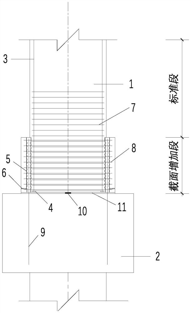
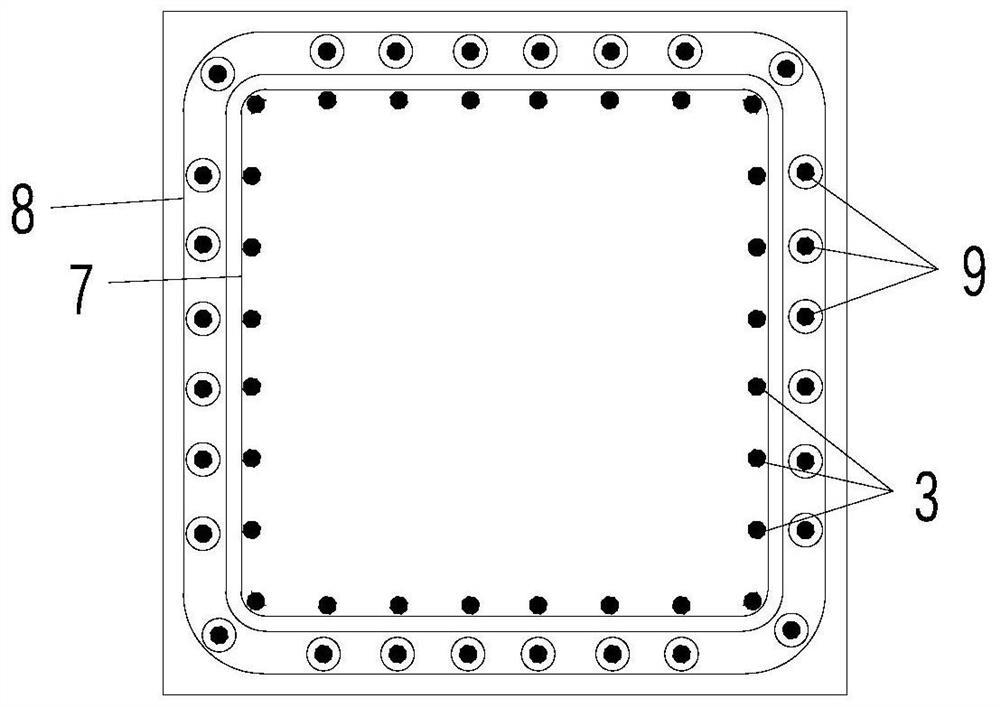
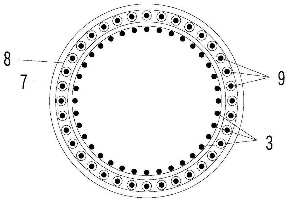
[0025] In one embodiment, combined with figure 1 , provides a connection structure between the prefabricated pier column and the cap, including the column 1 and the cap 2, the column 1 includes an increased section and a standard section, wherein the increased section is in contact with the cap 2, and the increased section The cross-sectional size is greater than the cross-sectional size of the standard section; a number of column steel bars 3 are arranged around the circumference of the column 1, and a threaded anchor head 4 is provided at the bottom end of the column ste...


PUM


Abstract

The invention discloses a prefabricated pier column and bearing platform connecting structure and a construction method. The structure comprises a stand column and a bearing platform, wherein the stand column comprises a section increasing section and a standard section, and the size of the cross section of the section increasing section is larger than that of the standard section; a plurality ofstand column steel bars and corrugated pipes are arranged on the circumference in the stand column and on the circumference in the section increasing section respectively, the corrugated pipes are located between the inner surface of the section increasing section and the stand column steel bars and close to the stand column steel bars, and threaded anchor heads are arranged at the bottom ends, which are close to the bearing platform, of the stand column steel bars; a grouting hole is formed in the lower part of the corrugated pipe, and an upper opening of the corrugated pipe is exposed in airas a grout outlet; inner-layer stirrups and outer-layer stirrups are arranged on the annular outer sides formed by the stand column steel bars and the corrugated pipes respectively; a plurality of pre-buried steel bars are arranged on the circumference in the bearing platform, and the pre-buried steel bars extend out of the bearing platform to be inserted into the corrugated pipes. According to the connecting structure, complex and high-precision prefabrication control requirements are not needed, construction operation is convenient, no special process and equipment requirements exist, and meanwhile, the static force and anti-seismic property of piers can be greatly improved.

Description

technical field [0001] The invention relates to the technical field of bridge construction, in particular to a connection structure and construction method of a prefabricated bridge pier column and cap. Background technique [0002] At present, the commonly used steel bar connection methods between prefabricated pier columns and caps mainly include: grouting sleeve connection method, grouting bellows anchor connection method and socket connection method. The grouting sleeve can be used to connect steel bars at the bottom of the prefabricated pier column, but the cost of the grouting sleeve is high, and the positioning accuracy of the sleeve and the pre-embedded steel bar of the cap are very high during prefabrication, and the sleeve is buried inside the pier column as a whole. Quality control is difficult and difficult to detect. The use of grouted bellows connection is actually an anchoring method for pier column reinforcement, so the bellows must be pre-embedded in the ca...

Claims


Application Information

Patent Timeline
Patent Type & Authority Applications(China)
IPC IPC(8): E01D21/10E01D19/02E01D101/26
CPCE01D19/02E01D21/10E01D2101/26
Inventor 姚宇韩大章周青姚凯傅晨曦严伟周童韩国顺杨鹏王贺鑫曹孙林
Owner JIANGSU PROVINCIAL COMM PLANNING & DESIGN INST
Why Eureka
Try Eureka