Pumping soluble plug

A pumping and bridge plug technology, which is applied in the field of pumping soluble plugs, can solve the problems of unsuitable inclined well operation, high operating cost, and long operating time, so as to eliminate operating hidden dangers, save operating time, and reduce operating time. The effect of fees

Pending Publication Date: 2020-10-13
深圳百途石油技术服务有限公司
View PDF0 Cites 1 Cited by
  • Summary
  • Abstract
  • Description
  • Claims
  • Application Information

AI Technical Summary

Problems solved by technology

However, there are many deficiencies in wire operation: long operation time, high operation cost, not suitable for inclined shafts and hidden dangers in operation (such as: knotting, falling off, easy to be caught by hooks)

Method used


Image

  • Pumping soluble plug
  • Pumping soluble plug
  • Pumping soluble plug

Examples


Embodiment Construction

[0018] The present invention will be described in further detail below in conjunction with the accompanying drawings.

[0019] This specific embodiment is only an explanation of the present invention, and it is not a limitation of the present invention. Those skilled in the art can make modifications to this embodiment as required after reading this specification, but as long as they are within the rights of the present invention All claims are protected by patent law.

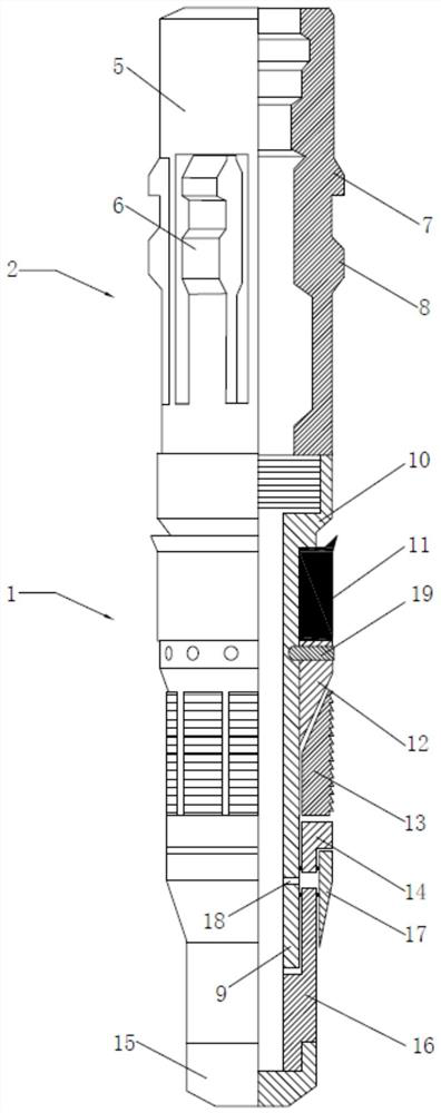
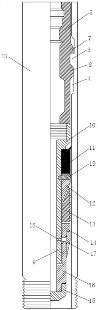
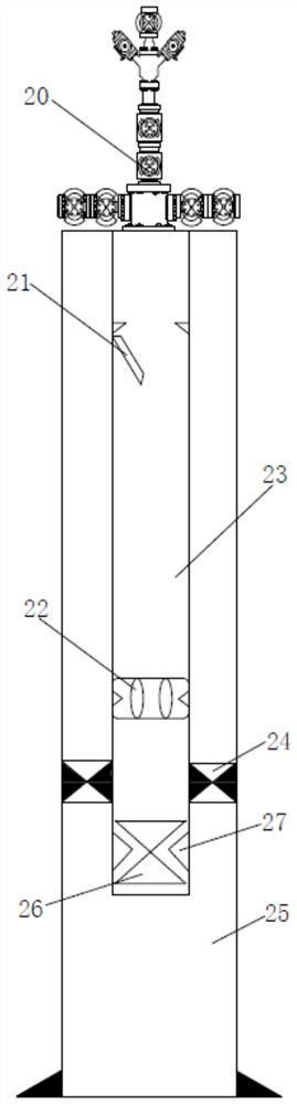
[0020] This embodiment relates to a pumping soluble plug, such as figure 1 As shown, it includes: a soluble bridge plug 1 and a soluble locking device 2 . The soluble locking device 2 is assembled on the soluble bridge plug 1, and under the action of pressure or its own gravity, it carries the soluble bridge plug 1 to reach and lock it at the preset short joint 27. Under the action of the hydraulic pressure in the oil pipe 23 , the soluble bridge plug 1 is located in the oil pipe 23 at the preset nipple 27 ....


PUM


Abstract

The invention discloses a pumping soluble plug, and relates to the technical field of oil and gas well tools. The pumping soluble plug comprises a soluble bridge plug and a soluble locking device, thesoluble bridge plug can be located on the preset locating short section in an oil pipe under the hydraulic pressure effect in the oil pipe, the soluble locking device is assembled on the soluble bridge plug, is located on the upper end of the soluble bridge plug during use, and carries the soluble bridge plug under the effect of pressurizing or self gravity to arrive at and be locked on the preset locating short section, multiple steps are mounted on the preset locating short section, the soluble locking device comprises a shaft body assembled at one end of the soluble bridge plug and multiple elastic buckling parts mounted on the outer side of the shaft body and used for being buckled on the steps, and through the technical scheme, the advantages of removing work hidden dangers of steelwire work, saving work time, reducing work cost and being wide in application range are achieved.

Description

technical field [0001] The invention relates to the technical field of oil and gas well tools, in particular to a pumping soluble plug. Background technique [0002] In the current well completion operation, in order to protect the casing, it is generally necessary to run a packer to isolate the oil and gas in the lower production layer. Existing production packers generally adopt hydraulic setting. During the setting process, a temporary plug needs to be lowered under the oil pipe to block the bottom of the oil pipe. After the setting is completed, it is taken out to ensure that the oil and gas flow from the oil pipe to the ground. After the oil pipe is pressed and sealed, the temporary plug below is taken out to ensure that the oil and gas flow from the oil pipe to the ground. As a result, at least 2-4 slickline operations are required to complete the setting of the production packer. However, there are many deficiencies in the steel wire operation: long operation time, ...

Claims


Application Information

Patent Timeline
Patent Type & Authority Applications(China)
IPC IPC(8): E21B33/134E21B33/126
CPCE21B33/1265E21B33/134
Inventor 沈夺为
Owner 深圳百途石油技术服务有限公司
Why Eureka
Try Eureka