Water level measuring system based on thermal imaging and measuring method thereof

A technology of water level measurement and infrared imaging system, which is applied in the direction of measuring device, transmission system, optical radiation measurement, etc. It can solve the problems of easy damage and short service life, and achieve the effects of good stability, low installation cost and easy maintenance

Pending Publication Date: 2020-10-13
中科信德建设有限公司
View PDF12 Cites 0 Cited by
  • Summary
  • Abstract
  • Description
  • Claims
  • Application Information

AI Technical Summary

Problems solved by technology

[0004] The purpose of the present invention is to overcome the problems of short service life and easy damage of existing water level measurement methods, and provide a water level measurement system and its measurement method based on thermal imaging

Method used


Image

  • Water level measuring system based on thermal imaging and measuring method thereof
  • Water level measuring system based on thermal imaging and measuring method thereof
  • Water level measuring system based on thermal imaging and measuring method thereof

Examples


Embodiment 1

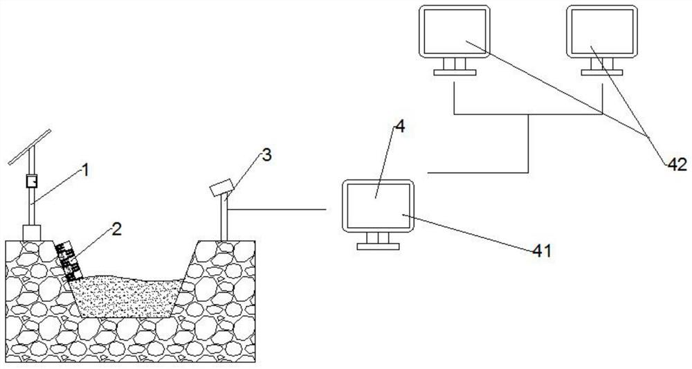
[0025] Such as Figure 1~3 As shown, a water level measurement system based on thermal imaging includes a power supply system 1, a water level gauge 2, an infrared imaging system 3 and a remote monitoring system 4, and the power supply system 1 is installed on a river revetment; the water level gauge 2 is fixedly installed In the river slope; the infrared imaging system 3 is installed on the river revetment opposite the water level gauge 2; the power supply system 1 is electrically connected to the water level gauge 2; the remote monitoring system 4 is electrically connected to the infrared imaging system 3 .

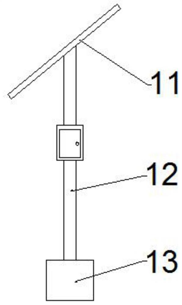
[0026] The power supply system 1 includes a solar photovoltaic panel 11, a support frame 12 and a storage battery 13; the solar photovoltaic panel 11 is obliquely installed on the top of the support frame 12; The bottom of the frame 12; the solar photovoltaic panel 11 is electrically connected to the charging interface of the storage battery 13; the power transmission ...

Embodiment 2

[0034] A water level measurement method based on thermal imaging, comprising the following steps:

[0035] (1) Fix the water level gauge on the channel or river slope to be measured;

[0036] (2) Install the power supply system on the canal or river revetment near the water level gauge, and electrically connect the water level gauge;

[0037] (3) Install the infrared imaging system on the revetment on the opposite side of the slope where the water level gauge is located, and adjust the detection head of the infrared imaging system so that the detection head points to the water level gauge;

[0038] (4) The data output terminal of the infrared imaging system is electrically connected to the remote monitoring system;

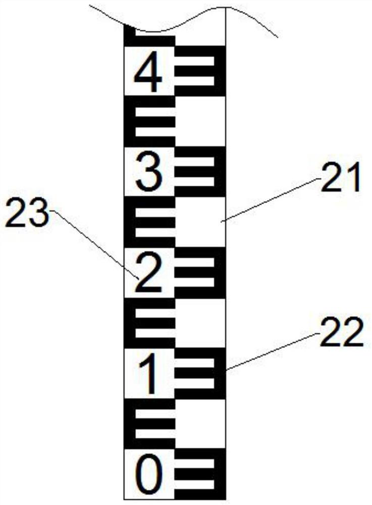
[0039] (5) The power supply system supplies power to the water level gauge, the heating element on the water level gauge generates heat, and the infrared imaging system monitors the heating of the heating element on the water level gauge;

[0040] (6) When the h...


PUM


Abstract

The invention discloses a water level measuring system based on thermal imaging and a measuring method thereof. The water level measuring system comprises a power supply system, a water gauge, an infrared imaging system and a remote monitoring system; the power supply system is installed on a river revetment; the water level gauge is fixedly mounted in a river slope; the infrared imaging system ismounted on a river channel revetment on the opposite side of the water level gauge; the power supply system is electrically connected with the water gauge; and the remote monitoring system is electrically connected with the infrared imaging system. The system can continuously and automatically detect the water level for a long time, and has the advantages of loose environmental requirements, lowinstallation cost, good stability, simple maintenance and the like. The system can be applied to scenes with water level measurement requirements, such as rivers, reservoirs, lakes, rivers, hydropowerstations and irrigation district drainage basins. By means of the system, the water level of a riverway or a canal can be accurately measured, errors are fixed, and the errors cannot be changed alongwith range expansion.

Description

technical field [0001] The invention relates to the technical field of water level measurement, in particular to a thermal imaging-based water level measurement system and a measurement method thereof. Background technique [0002] my country has a vast territory and many water areas. When severe weather occurs, if accurate and effective water level monitoring is not carried out in time, the water level will exceed the warning line, which will cause serious waterlogging disasters. Therefore, it is necessary to detect the water level of the river or dam in real time, and when the water level exceeds the warning level, it is necessary to open the gate to release the water. [0003] There are many methods for water level measurement in my country's water conservancy construction, such as: slope paint water gauge, ceramic tile embedded water gauge, stainless steel water gauge, water level measurement well, etc., all because the durability of use cannot be guaranteed or due to wa...

Claims


Application Information

Patent Timeline
Patent Type & Authority Applications(China)
IPC IPC(8): G01F23/04G01J5/00H04L29/08
CPCG01F23/04G01J5/00H04L67/025G01J2005/0077
Inventor 郭凌刘忠伟
Owner 中科信德建设有限公司
Why Eureka
Try Eureka