Check patentability & draft patents in minutes with Patsnap Eureka AI!

Key mechanism

A technology of buttons and keycaps, applied in tactile feedback, electrical components, electric switches, etc.

Inactive Publication Date: 2020-10-13
PIXART IMAGING INC
View PDF0 Cites 0 Cited by
  • Summary
  • Abstract
  • Description
  • Claims
  • Application Information

AI Technical Summary

Problems solved by technology

However, when the keycap 62 is pressed downwards, the traditional mechanical key 60 uses the cylinder in the keycap 62 to contact the switch 70, and the user can only feel a certain pressing feeling during the operation stroke of the traditional mechanical key, so how to design a The button mechanism with multi-stage control function is one of the key development goals of the related mechanism design industry

Method used


Image

  • Key mechanism
  • Key mechanism
  • Key mechanism

Examples


Embodiment Construction

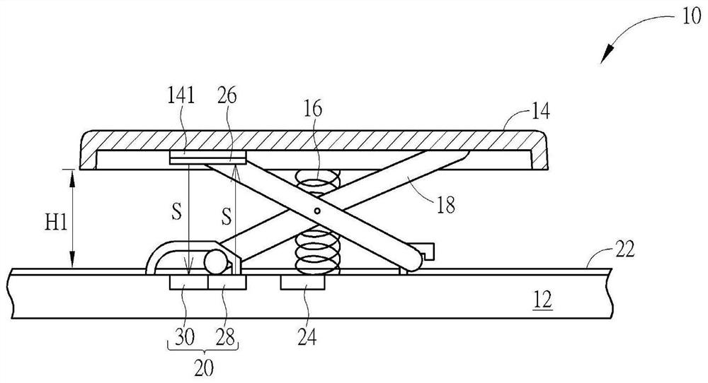
[0015] see figure 1 , figure 1 It is a schematic diagram of the button mechanism 10 of the embodiment of the present invention. The key mechanism 10 may include a substrate 12 , a keycap 14 , an elastic component 16 , a support component 18 , an optical detection module 20 , a thin film circuit board 22 and a processor 24 . The keycap 14 may have a reflective component 26 disposed on the base 141 of the keycap 14 . The base 141 can be an inner surface of the keycap 14 . The reflection component 26 can be disposed on the base 141 by coating or pasting. The elastic component 16 can be disposed between the base plate 12 and the keycap 14 . When the external force applied to the keycap 14 is removed, the elastic restoring force of the elastic component 16 can be used to move the keycap 14 back to the original position. Two ends of the supporting component 18 can be respectively connected to the substrate 12 and the keycap 14 for supporting and positioning the keycap 14 .

...


PUM


Abstract

The invention discloses a key mechanism capable of identifying whether a keycap is replaced or not. The key mechanism comprises a substrate, a keycap, an elastic assembly, an optical detection moduleand a processor. The keycap is arranged on the substrate, and the keycap is provided with a reflection assembly. The elastic assembly is arranged between the substrate and the keycap. The optical detection module is arranged on the substrate and is used for receiving the optical signals reflected by the reflection assembly. The processor is arranged on the substrate and is electrically connected with the optical detection module. The processor is configured to analyze the optical signal to obtain the movement information and the type information of the keycap. A user can replace the reflectionassembly or the keycap with the reflection assembly so as to adjust the operation mode of the key mechanism and change the use hand feeling of the key mechanism. Therefore, the key mechanism providedby the invention can effectively identify the reflection coefficient and the reflection assembly and the key cap thereof so as to determine how to switch and trigger the operation mode of the key mechanism.

Description

technical field [0001] The invention relates to a key mechanism, in particular to a key mechanism capable of identifying whether a keycap is replaced. Background technique [0002] see Image 6 , Image 6 It is a mechanical button 60 in the prior art. The keycap 62 of the conventional mechanical key 60 moves relative to the base plate 64 through the lifting unit 66 . When the keycap 62 is pressed and moves downward relative to the support member 64 , the elastic component 68 is elastically deformed to contact the switch 70 on the substrate 64 to form a conductive path and output an activation signal. The actuation signal is analyzed to obtain control instructions for the pressed mechanical key 60 . However, when the keycap 62 is pressed downwards, the traditional mechanical key 60 uses the cylinder in the keycap 62 to contact the switch 70, and the user can only feel a certain pressing feeling during the operation stroke of the traditional mechanical key, so how to design ...

Claims


Application Information

Patent Timeline
IPC IPC(8): H01H13/02H01H13/83H01H13/84
CPCH01H13/023H01H13/83H01H13/84H01H2215/044
Inventor 王聪法张彥闵
Owner PIXART IMAGING INC
Features
  • R&D
  • Intellectual Property
  • Life Sciences
  • Materials
  • Tech Scout
  • Unparalleled Data Quality
  • Higher Quality Content
  • 60% Fewer Hallucinations
Learn More