
Commutation failure suppression method for non-faulty strata converters in stratified access uhvdc system

A commutation failure, layered access technology, applied in the direction of AC network circuit, power transmission AC network, emergency treatment AC circuit layout, etc. voltage sag and other problems, to achieve the effect of improving transient response characteristics, suppressing commutation failure, and reducing power fluctuations

Active Publication Date: 2022-07-26
HEFEI UNIV OF TECH +1
View PDF1 Cites 0 Cited by
  • Summary
  • Abstract
  • Description
  • Claims
  • Application Information

AI Technical Summary

Problems solved by technology

[0003] 1) There is electrical coupling between the two AC power grids connected to the receiving end. When the voltage of one of the power grids is disturbed, the voltage of the other power grid will drop or be distorted, thereby affecting the normal operation of the converter. Low-end converters will fail commutation due to fluctuations in commutation voltage;
[0004] 2) The DC sides of the high-end and low-end converters are connected in series so that the DC currents of the two converters are the same. When a commutation failure occurs in one converter, the DC current will increase rapidly, thereby affecting the normal commutation of the other converter , causing the commutation failure of the high-end and low-end converters at the same time
However, in the currently published patents, the coordinated control of the high-end and low-end converters proposed in the layered access mode seldom comprehensively considers the AC voltage and DC current of the grid that cause commutation failure, which affects the judgment of commutation failure Accuracy, the control strategy to suppress commutation failure needs to be further improved

Method used


Image

  • Commutation failure suppression method for non-faulty strata converters in stratified access uhvdc system
  • Commutation failure suppression method for non-faulty strata converters in stratified access uhvdc system
  • Commutation failure suppression method for non-faulty strata converters in stratified access uhvdc system

Examples


Embodiment Construction

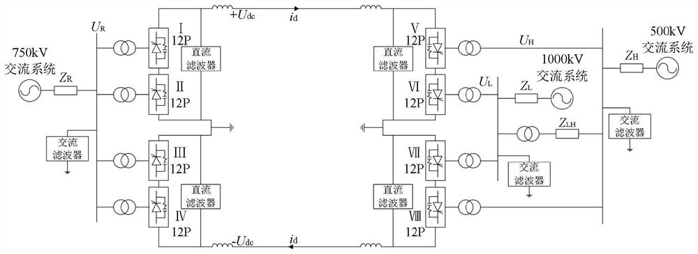
[0034] In this embodiment, as figure 1 As shown, the bipolar UHVDC system is sequentially composed of the sending-end AC power grid, the rectifier station, the transmission line, the inverter station, and the receiving-end AC power grid. where U dc is the unipolar rated voltage of the UHVDC system, i d is the rated DC current. Under normal operation, the DC side voltage of each 12-pulse converter is U dc / 2, the DC current flowing through is i d . The sending-end converter works in the rectification state, and the AC side is connected to the 750kV AC system through the commutation converter; the receiving-end converter works in the inverter state, and the high-end converter near the pole busbar is connected to the 500kV AC system through the commutation converter. The busbar, the low-end converter near the grounding point is connected to the 1000kV AC busbar through commutation, and then connected to the AC system AC1 and AC2 respectively, and equipped with AC filters of ...


PUM


Abstract

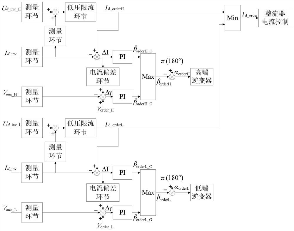
The invention discloses a commutation failure suppression method for layered access to non-faulty layer converters of a UHVDC system. AC system voltage disturbance; if the collected analog quantity exceeds the set value, the constant turn-off area control is performed; 2. The AC side fault layer and the non-fault layer are discriminated, and the DC current of the non-fault layer converter is increased 3. After the fault is cleared, restore the cut-off angle to the rated value, and release the output limit of the trigger lead angle. The invention can effectively suppress the commutation failure of the non-faulty layer converters of the layered access UHVDC system, thereby improving the transient response characteristics of the system during the fault period, reducing the power fluctuation caused by the commutation failure of the inverter station, and reducing the impact on the AC Grid shock.

Description

technical field [0001] The invention relates to a method for suppressing the commutation failure of a non-faulty layer converter of a layered access UHVDC system, and belongs to the technical field of high-voltage direct current transmission. Background technique [0002] With the increasing demand for large-capacity and long-distance power transmission, HVDC transmission based on grid commutation converters has been widely used in DC power transmission projects due to its outstanding economical and long-distance power transmission advantages. The inverter based on grid commutation uses thyristor without self-shutdown capability as the commutation element. When the voltage of the receiving end grid is disturbed, the commutation failure is very likely to occur, which is easy to cause large fluctuations in power transmission and seriously threaten the security of the grid. In recent years, the transmission power of UHV DC transmission has been increasing continuously. In order...

Claims


Application Information

Patent Timeline
Patent Type & Authority Patents(China)
IPC IPC(8): H02J3/36H02J3/00
CPCH02J3/36H02J3/001H02J2003/365H02J2203/20Y02E60/60
Inventor 韩平平孙浩然童青洋张炎杨为陈忠李宾宾王欢王希
Owner HEFEI UNIV OF TECH
Learn More