
Direct current welding machine control circuit with output current rotating forwardly and reversely

A DC welding machine and control circuit technology, applied in the direction of welding power source, etc., can solve the problems of the influence of the quality of the solder joints, the welding head is easily damaged, and the loss, etc., and achieve the effect of solving the polarity effect.

Active Publication Date: 2020-10-16
珠海微点焊电子工业有限公司
View PDF6 Cites 0 Cited by
  • Summary
  • Abstract
  • Description
  • Claims
  • Application Information

AI Technical Summary

Problems solved by technology

[0002] For the current electronic DC welding machines on the market, after a period of welding, one side of the tip of the two poles of the welding head will have a larger loss than the other, causing the welding head to be easily damaged and the quality of the solder joints will be affected. This is because the existing DC The current direction of the welding machine is single, and the direct current of a single direction will produce the polarity effect to cause the above-mentioned problem, and this problem is a major defect of the existing direct current welding machine

Method used


Image

  • Direct current welding machine control circuit with output current rotating forwardly and reversely
  • Direct current welding machine control circuit with output current rotating forwardly and reversely
  • Direct current welding machine control circuit with output current rotating forwardly and reversely

Examples


Embodiment Construction

[0019] The present invention will be described in detail below with reference to the accompanying drawings and examples. It should be noted that in the case of no conflict, the following embodiments and the features in the embodiments can be combined with each other.

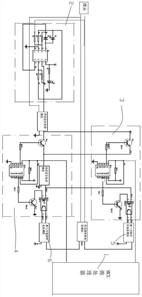
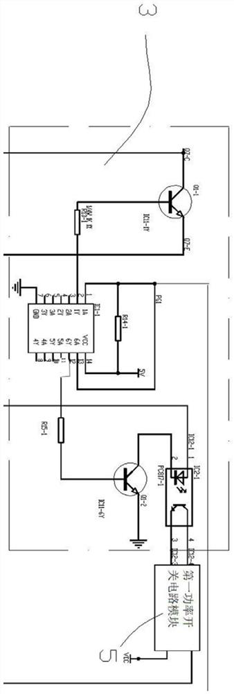
[0020] Such as Figure 1-4 As shown, a control circuit for forward and reverse output current DC welding machine, including MCU microprocessor 1, polarity processing circuit module 2, first power drive circuit module 3, second power drive circuit module 4, first power switch The circuit module 5, the second power switch circuit module 6 and the transformer conversion circuit module 7, wherein the transformer conversion circuit module adopts a tapped transformer.

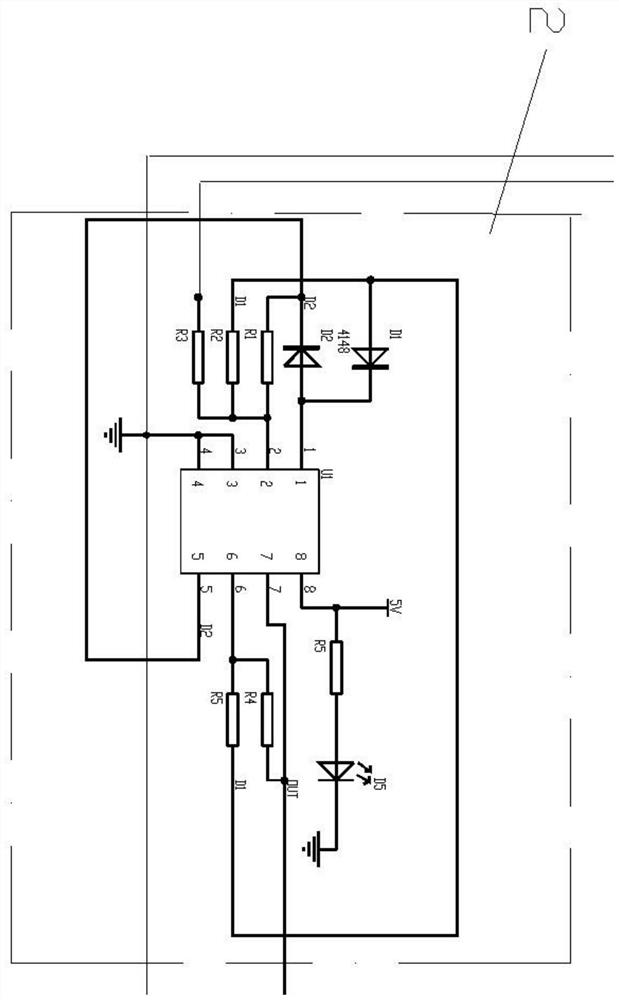
[0021] The signal input terminal of the polarity processing circuit module 2 is connected to two electrical signals with the same amplitude and opposite polarity output by the welding machine, and the output terminals of the polarity processing circui...


PUM


Abstract

The invention discloses a direct current welding machine control circuit with output current rotating forwardly and reversely. The control circuit is characterized by comprising a micro control unit,a polarity processing circuit module, a first power drive circuit module, a second power drive circuit module, a first power switch circuit module, a second power switch circuit module and a transformer conversion circuit module. According to the direct current welding machine control circuit with the output current rotating forwardly and reversely, the circuit controls the front welding period and the rear welding period to output electric signals in different current directions, so that the polarity effect of a welding head is avoided, the service life of the welding head is prolonged, and the welding spot quality is improved.

Description

technical field [0001] The invention relates to the technical field of resistance welding electronic welding machine electronic circuits, in particular to a control circuit for forward and reverse output current DC welding machines. Background technique [0002] For the current electronic DC welding machines on the market, after a period of welding, one side of the tip of the two poles of the welding head will have a larger loss than the other, causing the welding head to be easily damaged and the quality of the solder joints will be affected. This is because the existing DC The current direction of the welding machine is single, and the direct current of a single direction will produce the polarity effect and cause the above-mentioned problem, and this problem is a major defect of the existing direct current welding machine. Contents of the invention [0003] Based on the deficiencies of the prior art, the present invention aims to provide a control circuit for forward an...

Claims


Application Information

Patent Timeline
IPC IPC(8): B23K11/24
CPCB23K11/24
Inventor 张淑燕
Owner 珠海微点焊电子工业有限公司
Learn More