
Air deflector for air conditioner and air conditioner

A technology for air deflectors and air conditioners, which is applied in air-conditioning systems, space heating and ventilation, space heating and ventilation details, etc. The effect of dew, the avoidance of condensation, the effect of improving the attracting ability

Pending Publication Date: 2020-10-16
QINGDAO HAIER AIR CONDITIONING ELECTRONICS CO LTD +1
View PDF8 Cites 2 Cited by
  • Summary
  • Abstract
  • Description
  • Claims
  • Application Information

AI Technical Summary

Problems solved by technology

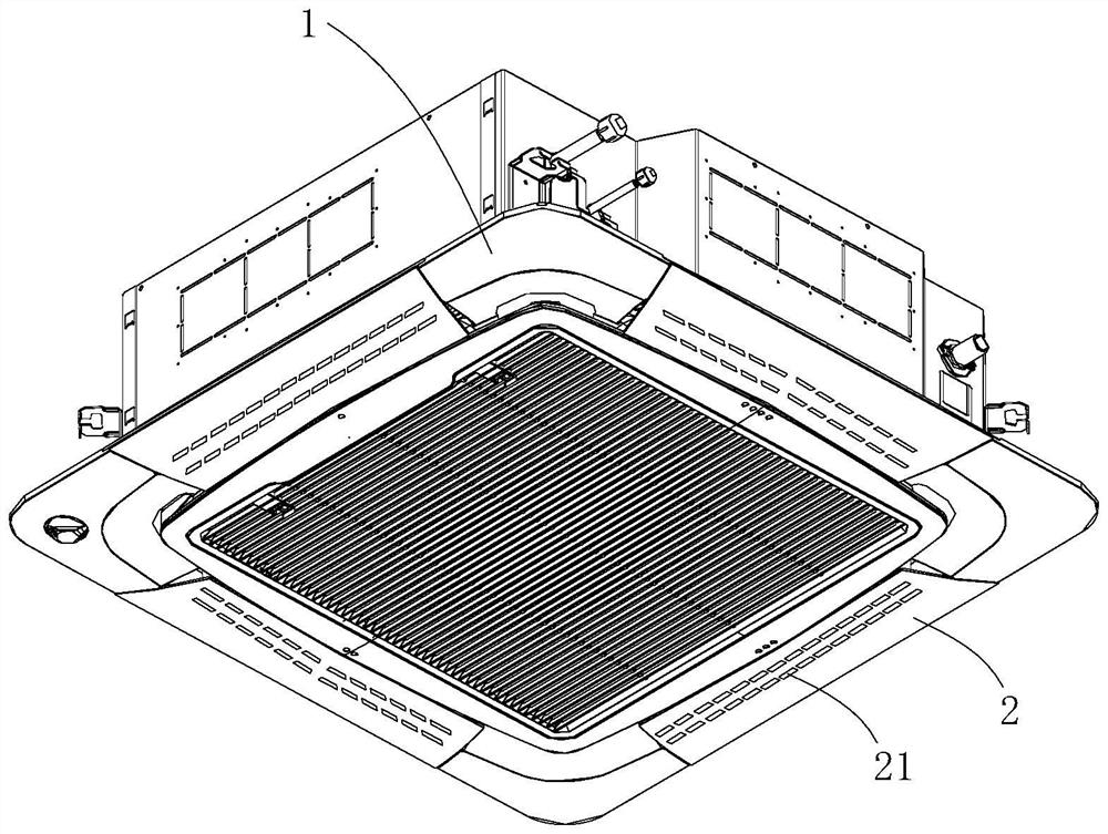
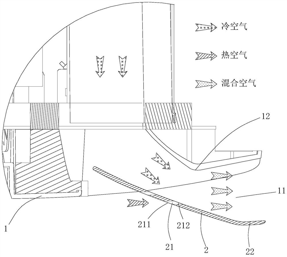
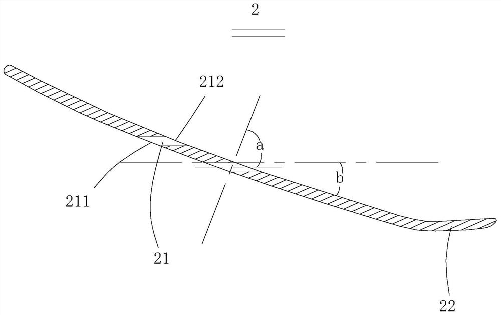
[0006] In order to solve the above-mentioned problems in the prior art, that is, in order to solve the problem that the outer surface of the air deflector of the existing air conditioner is prone to condensation, the present invention provides an air deflector for an air conditioner, the air conditioner Including an indoor unit, the casing of the indoor unit is provided with an air outlet, the air guide plate is arranged at the air outlet, the air guide plate is provided with an induction hole, and the air inlet of the induction hole The end is located on the outer surface of the wind deflector, the air outlet end of the induction hole is located on the inner surface of the air deflector, and the induction hole is from the air inlet end to the air outlet end toward the The front end of the air deflector is inclined so as to induce the air outside the air deflector to the inside of the air deflector and thus mix with the air in the air outlet when the air conditioner is in operation

Method used


Image

  • Air deflector for air conditioner and air conditioner
  • Air deflector for air conditioner and air conditioner
  • Air deflector for air conditioner and air conditioner

Examples


Embodiment Construction

[0033] First of all, those skilled in the art should understand that the embodiments described below are only used to explain the technical principles of the present invention, and are not intended to limit the protection scope of the present invention. For example, although the following embodiments are described in conjunction with embedded air conditioners, the present invention is still applicable to other air conditioners, such as wall-mounted air conditioners, etc., and the adjustment and change of such application objects do not depart from the principles of the present invention. The principle and scope should be limited within the protection scope of the present invention.

[0034] It should be noted that, in the description of the present invention, the terms "upper", "lower", "left", "right", "front", "rear", "inner", "outer", etc. indicate directions or positional relationships The terms are based on the orientation or positional relationship shown in the drawings,...


PUM

PropertyMeasurementUnit
Angleaaaaaaaaaa
Widthaaaaaaaaaa

Abstract

The invention belongs to the technical field of air conditioners and particularly relates to an air deflector for an air conditioner and the air conditioner. The air deflector is provided with a leading hole. The air inlet end of the leading hole is located on the outer surface of the air deflector. The air outlet end of the leading hole is located on the inner surface of the air deflector. The leading hole is inclined toward the front end of the air deflector from the air inlet end to the air outlet end, and thus when the air conditioner operates, air located on the outer side of the air deflector is led to the inner side of the air deflector, thereby being mixed with air in an air outlet. When the air conditioner is in cooling operation, the flow speed of the air in the air outlet is high, thus the air pressure of the inner side of the air deflector is lower than that of the outer side of the air deflector, hot air located on the outer side of the air deflector is sucked to the innerside of the air deflector and is mixed with cold air in the air outlet, the temperature of the air at the air outlet is increased accordingly, the temperature of the air deflector is not so low any more, the temperature of the air deflector is high, water in the air does not condense, and thus condensation can be prevented from being generated on the outer surface of the air deflector.

Description

technical field [0001] The invention belongs to the technical field of air conditioners, and specifically provides an air deflector for the air conditioner and the air conditioner. Background technique [0002] An air conditioner is a device capable of cooling and / or heating a room. [0003] The air conditioner includes an indoor unit and an outdoor unit, and the indoor unit includes a housing, an air outlet is arranged on the housing, and an air guide plate is arranged at the air outlet, through which the air outlet direction can be changed to expand the air supply range. However, when the air conditioner is in cooling operation, the temperature of the air deflector will be relatively low due to the influence of cold wind. However, the temperature of the indoor air is relatively high. When the hot air contacts the low temperature air deflector, the air in the hot air will Moisture is condensed, causing condensation on the outer surface of the air deflector. When there is a...

Claims


Application Information

Patent Timeline
IPC IPC(8): F24F1/0003F24F1/0011F24F1/0047F24F13/14F24F13/22
CPCF24F1/0003F24F1/0011F24F1/0047F24F13/14F24F13/22F24F2013/221
Inventor 刘新波李文波张吉义王元董德智
Owner QINGDAO HAIER AIR CONDITIONING ELECTRONICS CO LTD
Learn More