

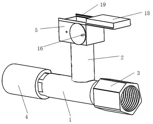
Pipe network hydraulic detection device
A hydraulic detection and pipe network technology, which is applied in the direction of measuring devices, applying stable tension/pressure to test the strength of materials, instruments, etc., can solve problems such as hand shaking, affecting measurement accuracy, and inconsistencies between parameters and actual values. Reduce the effect of error and fluctuation of external factors, and reduce the fluctuation of standard instrument
- Summary
- Abstract
- Description
- Claims
- Application Information
AI Technical Summary
Problems solved by technology
Method used
Image

Examples
Embodiment approach 2
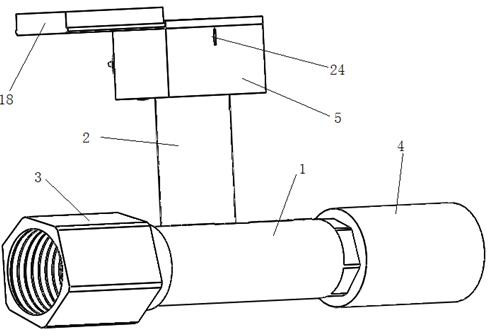
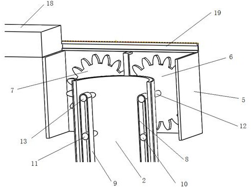
[0027]This embodiment is a further improvement of Embodiment 1. The main improvement is that in Embodiment 1, when the standard is transported by the transport mechanism, when will the probe at the bottom of the standard reach the transport tube 2 and the main tube 1 The junction of the connection cannot be accurately judged, and the detection probe protruding into the main pipe 1 too deep or too shallow will affect the accuracy of the measurement results. In this embodiment, however, it can be more accurately judged when the detection probe arrives at the joint between the delivery tube 2 and the main tube 1 .
[0028] Specifically, in the pipe network hydraulic pressure detection device in this embodiment, such as Figures 5 to 7 A positioning shaft 20 with a length shorter than the inner diameter of the delivery pipe 2 is also fixed laterally at the connection between the delivery pipe 2 and the main pipe 1, and a contact rod 21 with a length smaller than the inner diameter...
PUM
 Abstract
Description
Claims
Application Information