Combined antenna

A technology of combining antennas and antennas, which can be applied to antennas, antenna arrays, antenna components, etc., and can solve problems such as the inability to meet real-time high-precision positioning.

Active Publication Date: 2020-10-16
SHENZHEN DINGYAO SCI & TECH
View PDF10 Cites 1 Cited by
  • Summary
  • Abstract
  • Description
  • Claims
  • Application Information

AI Technical Summary

Problems solved by technology

[0002] With the continuous development of science and technology, mobile communication technology has also improved, and people are increasingly relying on real-time precise positioning technology, so the traditional GNSS positioning technology can no longer meet the needs o

Method used


Image

  • Combined antenna
  • Combined antenna
  • Combined antenna

Examples


Embodiment 1

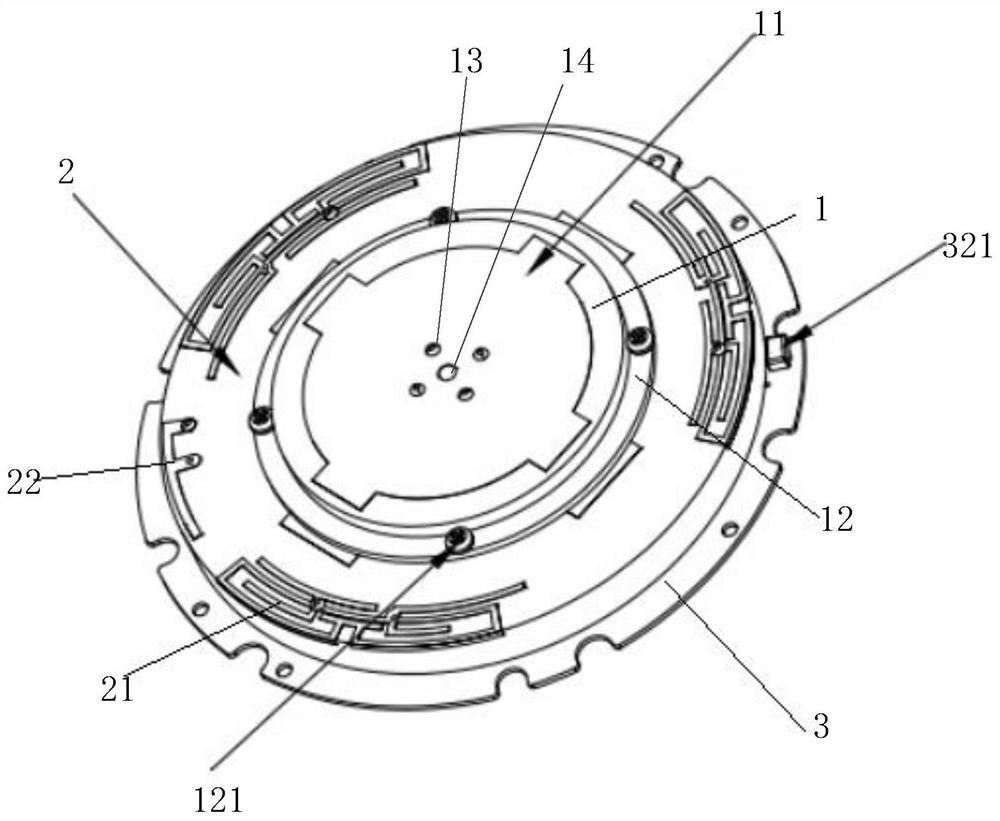
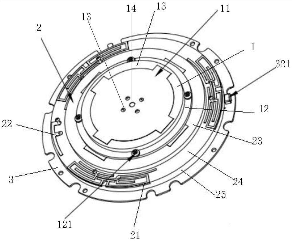
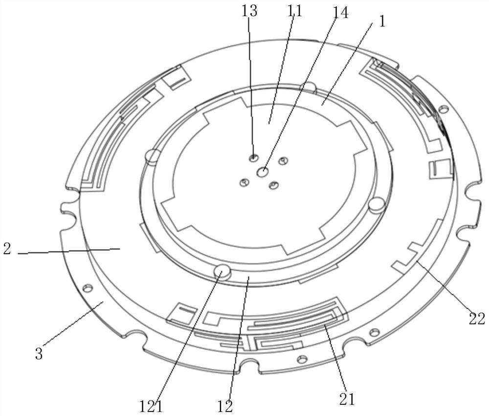
[0031] Please refer to figure 1 , a combination antenna provided in this embodiment, which includes a first mounting board 1, a second mounting board 2 and a circuit board 3, the second mounting board 2 is arranged on the upper surface of the circuit board 3, and the first mounting board 1 is arranged on the second The upper surface of the second mounting plate 2, and the second mounting plate 2 is larger than the first mounting plate 1 so that the surrounding and / or side faces of the upper surface of the second mounting plate 2 form the mounting position (ie, the mounting surface). The first mounting plate 1 upper surface is provided with positioning antenna 11, and the mounting position of the second mounting plate 2 is provided with at least two mobile communication antennas 21, and circuit board 3 is provided with positioning antenna 11 and mobile communication antenna 21 correspondences. The feeding circuit and the feeding needle, the positioning antenna 11 and the mobile...


PUM


Abstract

The invention relates to the technical field of radio frequency antennas, in particular to a combined antenna which comprises a first mounting plate, a second mounting plate and a circuit board, the second mounting plate is arranged on the upper surface of the circuit board, the first mounting plate is arranged on the upper surface of the second mounting plate, and the second mounting plate is larger than the first mounting plate, so that mounting positions are formed in the periphery and/or the side face of the upper surface of the second mounting plate. The upper surface of the first mounting plate is provided with a positioning antenna, and the mounting position of the second mounting plate is provided with at least two mobile communication antennas. According to the combined antenna, the positioning antenna is arranged in the center, the mobile communication antennas are arranged surrounding the positioning antenna; mutual influence between the mobile communication antennas and thepositioning antenna can be effectively enhanced; therefore, the stability of the phase center of the positioning antenna is ensured, the positioning antenna can be assisted by using the mobile communication antennas, an accurate positioning signal can be obtained in real time through a carrier phase difference technology, the high-precision measurement requirement in the industry is met, and theoperation efficiency is improved.

Description

technical field [0001] The invention relates to the technical field of radio frequency antennas, in particular to a combined antenna. Background technique [0002] With the continuous development of science and technology, mobile communication technology has also improved, and people are increasingly relying on real-time precise positioning technology, so the traditional GNSS positioning technology can no longer meet the needs of real-time high-precision positioning, so a combined antenna is needed to Instead of static GNSS measurement technology, the combined antenna can obtain accurate positioning signals in real time to meet the measurement needs of engineering stakeout and topographic mapping. Contents of the invention [0003] The present application provides a combined antenna, which aims to replace the existing GNSS positioning antenna to meet the demand for real-time high-precision positioning. [0004] A combined antenna, comprising a first mounting board, a seco...

Claims


Application Information

Patent Timeline
IPC IPC(8): H01Q1/12H01Q1/50H01Q1/22H01Q21/20H01Q21/30G01S19/46
CPCG01S19/46H01Q1/12H01Q1/225H01Q1/50H01Q21/205H01Q21/30
Inventor 温寨峰杨伟城俞江
Owner SHENZHEN DINGYAO SCI & TECH
Why Eureka
Try Eureka