
Integrated terminal

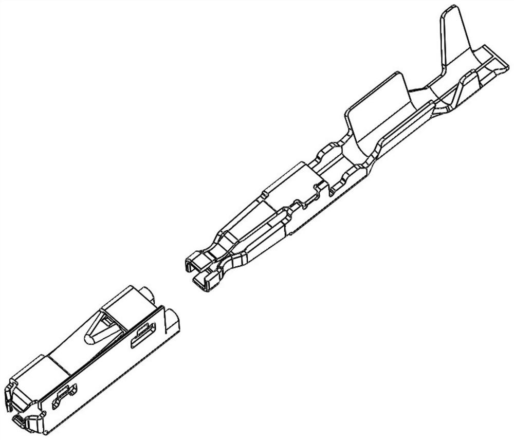
An all-in-one, terminal technology, applied in the direction of contact parts, etc., can solve the problems of increasing the difficulty of inter-plugging the terminal body and the metal shell, increasing the complexity of the design structure of the terminal body, increasing the cost of terminal manufacturing, etc., to achieve simplification. Molding route, good force stability, and the effect of reducing molding volume

Pending Publication Date: 2020-10-16
GOLDENCONN ELECTRONICS TECH CO LTD
View PDF0 Cites 0 Cited by
  • Summary
  • Abstract
  • Description
  • Claims
  • Application Information

AI Technical Summary

Problems solved by technology

In the actual manufacturing process of the terminal, the terminal body and the metal shell are punched and bent independently, and then the two are inserted into one body. In this way, on the one hand, the terminal forming requires a long process route, so that It reduces its production efficiency and increases its manufacturing cost; on the other hand, in order to ensure the anti-off property, it is necessary to add a limiting structure between the terminal body and the metal shell, thus increasing the terminal body and metal shell to a certain extent. The complexity of the design structure of the shell further increases the manufacturing cost of the terminal, and to a certain extent increases the difficulty of the inter-plug operation of the terminal body and the metal shell

Method used


Image

  • Integrated terminal
  • Integrated terminal
  • Integrated terminal

Examples


Embodiment Construction

[0024] In the description of the present invention, it should be understood that the orientations or positional relationships indicated by the terms "front", "rear", "upper", "lower", "left", "right" etc. are based on the Orientation or positional relationship is only for the convenience of describing the present invention and simplifying the description, and does not indicate or imply that the referred device or element must have a specific orientation, be constructed and operated in a specific orientation, and thus should not be construed as a limitation of the present invention.

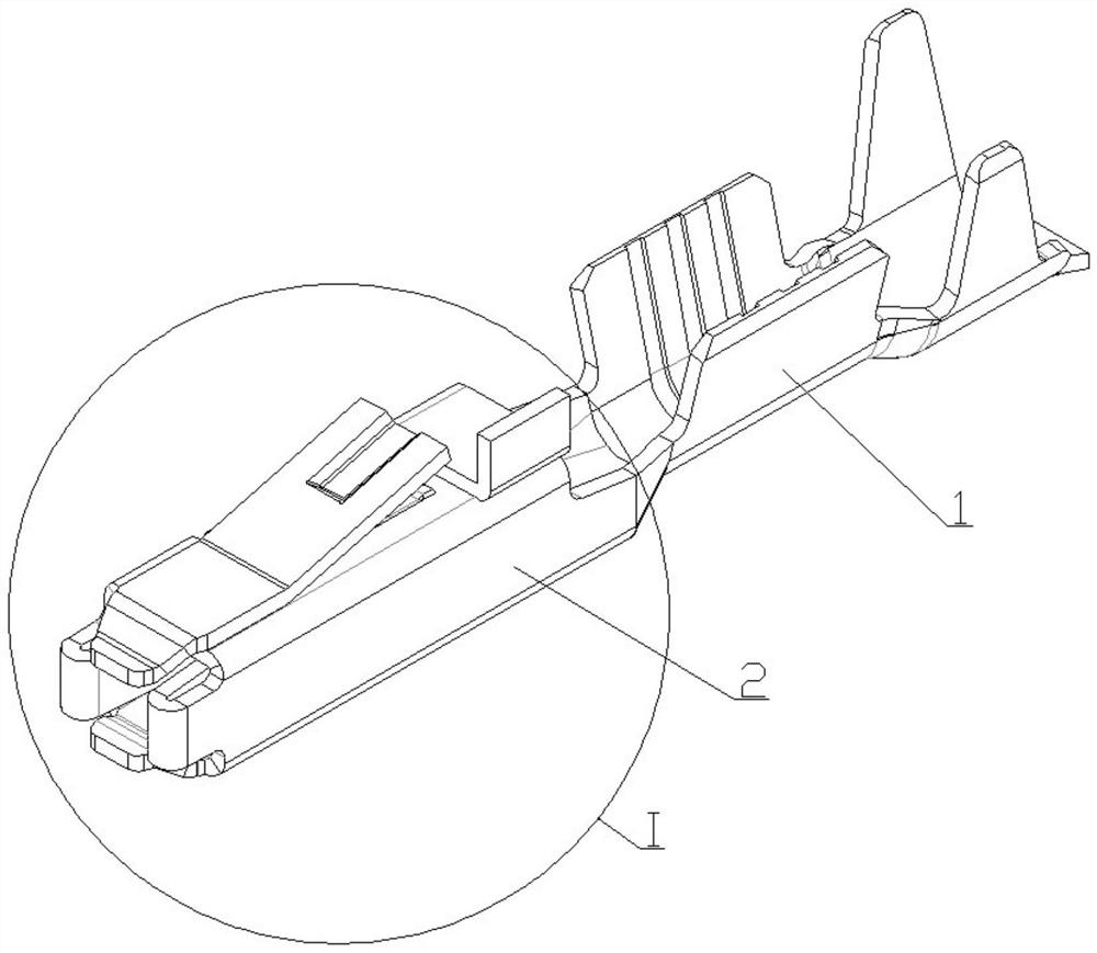
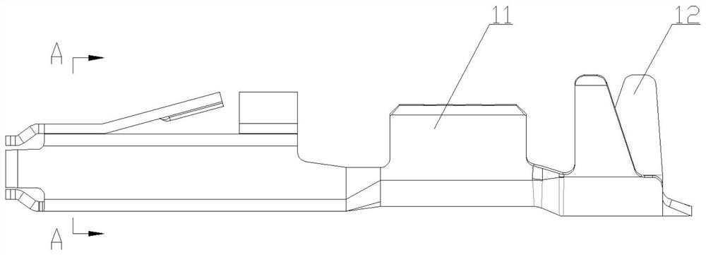
[0025] Below in conjunction with specific embodiment, content of the present invention is described in further detail, figure 2 A three-dimensional schematic diagram of a viewing angle of the integrated terminal in the present invention is shown. It can be seen that it is mainly formed by sequentially connecting the welding section 1 and the conductive core insertion section 2 . In addition, in c...


PUM


Abstract

The invention relates to an integrated terminal. The integrated terminal comprises a welding section and a conductive core inserting section which are connected in sequence, the conductive core inserting section comprises a first folding wall, a second folding wall, a third folding wall, a fourth folding wall, a fifth folding wall, a first plug-in mounting elastic sheet, a first plug-in mounting guide arm, a second plug-in mounting elastic sheet and a second plug-in mounting guide arm. The first folding wall, the second folding wall, the third folding wall and the fourth folding wall are sequentially connected in the clockwise direction so as to form a square cavity in a surrounding mode. The fifth folding wall is formed by continuously extending the fourth folding wall and bending the fourth folding wall by 90 degrees in the clockwise direction. The first plug-in mounting elastic sheet and the second plug-in mounting elastic sheet are oppositely arranged and are both arranged in the square cavity. The first plug-in mounting elastic sheet and the second plug-in mounting elastic sheet are respectively formed by continuously extending the second folding wall and the fourth folding wall forwards and bending in opposite directions. The first plug-in mounting guide arm and the second plug-in mounting guide arm are oppositely arranged and are formed by continuously extending forwardsand bending the third folding wall and the fifth folding wall respectively.

Description

technical field [0001] The invention relates to the technical field of electrical connector manufacturing, in particular to an integrated terminal. Background technique [0002] With the development of science and technology and the improvement of living standards, people's demand for electronic products is increasingly strong. Electrical connectors are widely used in power systems, communication networks, financial manufacturing, elevators, industrial automation, medical equipment, office equipment, home appliances, military manufacturing, automotive and other industries. They are mainly used to connect electronic products or between components in electronic products signal transmission. [0003] The electrical connector includes a main body plastic part and a plurality of terminals, wherein along its length direction, a plurality of jack holes are formed on the main body plastic part for inserting and fixing the above-mentioned terminals, thereby realizing signal transmis...

Claims


Application Information

Patent Timeline
Patent Type & Authority Applications(China)
IPC IPC(8): H01R13/02
CPCH01R13/02
Inventor 余开刚何志刚陈进嵩
Owner GOLDENCONN ELECTRONICS TECH CO LTD
Learn More