Application defined multi-tiered wear-leveling for storage class memory systems
A wear leveling and application technology, applied in memory system, memory architecture access/allocation, data processing input/output process, etc., can solve the problem of high wear and tear
- Summary
- Abstract
- Description
- Claims
- Application Information
AI Technical Summary
Problems solved by technology
Method used
Image

Examples
Embodiment Construction
[0036] It should be understood at the outset that although an illustrative implementation of one or more embodiments is provided below, the disclosed systems and / or methods may be implemented using any number of techniques, whether currently known or in existence. The disclosure should in no way be limited to the illustrative implementations, drawings, and techniques illustrated below, including the exemplary designs and implementations illustrated and described herein, but rather be limited by the scope of the appended claims and their equivalents Modified within the full range of .
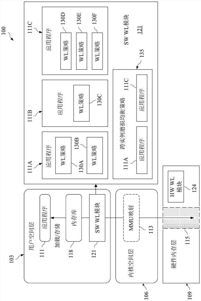
[0037] Wear leveling is the process of moving data so that it is stored at different physical addresses in memory at different times to prevent some memory cells from wearing out before others. Typical wear leveling methods are performed on memory in a coarse-grained manner, where thousands of bits change location during one iteration of wear leveling. Typical wear leveling methods also do not ...
PUM
 Abstract
Description
Claims
Application Information