Movable rotary type multifunctional integrated cabinet

A multi-functional and rotating technology, applied in the field of lockers, can solve the problems of single internal storage space planning, large space occupation, and poor aesthetics.

Pending Publication Date: 2020-10-20
山西建邦集团铸造有限公司
View PDF0 Cites 1 Cited by
  • Summary
  • Abstract
  • Description
  • Claims
  • Application Information

AI Technical Summary

Problems solved by technology

[0006] In view of this, the object of the present invention is to provide a movable and rotating multifunctional integrated cabinet to solve the problems of large occupied space, poor aesthetics, difficulty in moving and

Method used


Image

  • Movable rotary type multifunctional integrated cabinet
  • Movable rotary type multifunctional integrated cabinet
  • Movable rotary type multifunctional integrated cabinet

Examples


Embodiment 1

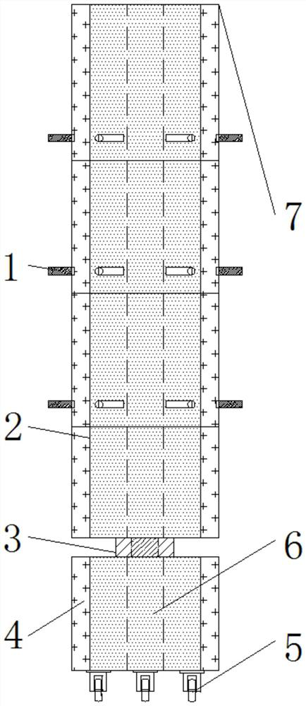
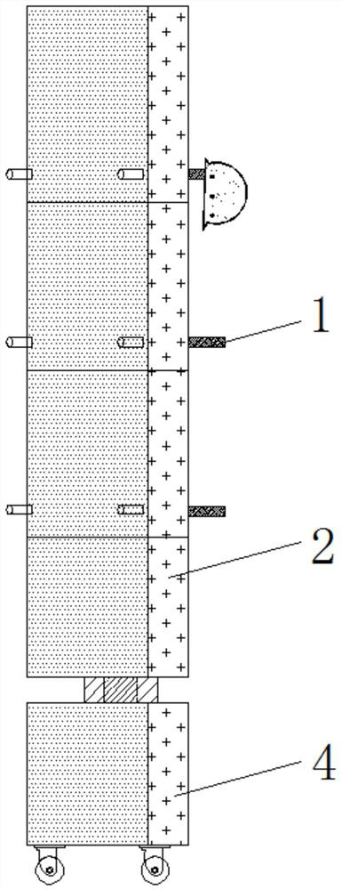
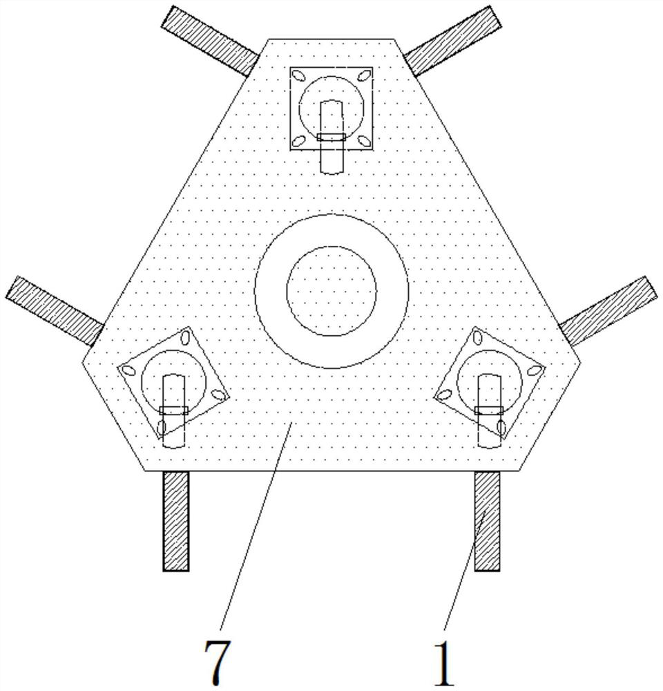
[0027] Such as Figure 1-5 As shown, the movable rotating multifunctional integrated cabinet includes an upper storage tank 2, a lower storage tank 4, a main body 7 and a moisture-proof box 9. The main body 7 is provided with upper and lower parts, and the connection between the upper and lower parts of the main body 7 A rotating shaft 3 is provided, and the rotating shaft 3 is a rolling bearing structure. The upper part of the main body 7 is connected with the outer ring of the rotating shaft 3, and the lower part of the main body 7 is connected with the inner ring of the rotating shaft 3. The upper part of the main body 7 can be relatively The lower part of the main body 7 rotates 360 degrees, the outer wall of the main body 7 is uniformly welded with a hook 1, the upper part of the main body 7 is evenly provided with an upper storage groove 2, and the inner part of the lower part of the main body 7 is evenly provided with The lower storage tank 4, and one side of the upper ...

Embodiment 2

[0030] Based on the structure of Example 1, in Example 2, such as Figure 4 As shown, the bottom end inside the upper storage tank 2 is provided with a second storage tank 202, and the top inside the upper storage tank 2 is provided with a first storage tank 201, and both ends of the storage drawer 10 are uniformly welded with sliders, Moreover, a pull-out structure is formed between the storage drawer 10 and the main body 7 , a cover plate 8 is hinged on the top end of the storage drawer 10 , and a latch 11 is provided between the cover plate 8 and the storage drawer 10 .

[0031] During use, on the one hand, the user can hang some long clothes on the hanger 15 at the top of the first storage tank 201 to avoid wrinkles of the clothes, and can hang some anti-wrinkle items. Use the fixing clip 16 to fix it inside the first storage slot 201. On the other hand, you can place valuables such as wallets inside the storage drawer 10, and close the cover plate 8 and the lock buckle 11...

Embodiment 3

[0033] Based on the structure of Example 1, in Example 3, as Figure 4-5 As shown, one side of the moisture-proof box 9 is evenly welded with a reserved insert 19, the inside of the main body 7 is provided with a reserved slot 20 that matches the reserved insert 19, and the reserved insert 19 is provided with The fixed bolt 18 that is connected with the main body 7.

[0034]When in use, the user can use the sliding connection structure formed by the reserved insertion strip 19 and the reserved slot 20, and cooperate with the locking and fixing effect of the fixing bolt 18 to disassemble the moisture-proof box 9 and the main body 7, which is convenient for the user. The activated carbon drying block 17 inside the moisture-proof box 9 is replaced.


PUM


Abstract

The invention discloses a movable rotary type multifunctional integrated cabinet. The integrated cabinet comprises upper storage grooves, lower storage grooves, a main body and damp-proof boxes, and the main body is provided with an upper part and a lower part. A rotating shaft is arranged at the joint of the upper and lower parts of the main body; meanwhile, the rotating shaft is of a rolling bearing structure, the upper part of the main body is connected with the outer ring of the rotating shaft; the lower part of the main body is connected with the inner ring of the rotating shaft; hooks are evenly welded to the outer side wall of the main body, the lower storage grooves are evenly formed in the bottom end of the interior of the main body, the upper storage grooves are evenly formed inthe top end of the interior of the main body, door bodies are hinged to one sides of the upper storage grooves and one sides of the lower storage grooves, and the damp-proof boxes are installed at thetwo ends of the interiors of the upper storage grooves and the lower storage grooves. The upper portion of the integrated cabinet can be rotated by 360 degrees, the integrated cabinet is placed at awall corner when not used, attractiveness and elegance are achieved, when objects are taken, the upper portion can be rotated to be switched to the upper containing grooves in different positions of the upper portion of the integrated cabinet, the objects are convenient to take, and simplicity and convenience are achieved.

Description

technical field [0001] The invention relates to the technical field of storage cabinets, in particular to a movable and rotating multifunctional integrated cabinet. Background technique [0002] Industrial sites often require fixed installation of some lockers to facilitate workers to store clothes, shoes and hats or other items, but the existing lockers still have the following problems in actual use: [0003] 1. Ordinary lockers not only take up a lot of space, but also are extremely unsightly and difficult to move and access items, which leads to poor use of the device; [0004] 2. The existing lockers on the market still have a single internal storage space planning and are not easy to classify storage, which makes the device unable to fully meet the needs of users; [0005] 3. Existing lockers also generally have the disadvantages of being difficult to prevent moisture and deodorize, and are difficult to repair and maintain, which leads to poor functionality of the dev...

Claims


Application Information

Patent Timeline
IPC IPC(8): A47B61/00A47B61/04A47B49/00A47B91/06A47B88/40A47B88/50A47B97/00B01D53/04
CPCA47B49/004A47B61/00A47B61/04A47B91/06A47B97/00A47B88/40A47B88/50B01D53/04
Inventor 韩华李明王富强
Owner 山西建邦集团铸造有限公司
Why Eureka
Try Eureka