
Assembly line plate overturning device

An assembly line and turnover technology, which is applied in the direction of transportation and packaging, conveyor objects, rollers, etc., can solve the problems of slow work efficiency, high labor cost, time-consuming and laborious, etc.

Inactive Publication Date: 2020-10-20
杨祝信
View PDF3 Cites 1 Cited by
  • Summary
  • Abstract
  • Description
  • Claims
  • Application Information

AI Technical Summary

Problems solved by technology

[0002] Boards are made into standard-sized flat rectangular building material boards, used in the construction industry as components of walls, ceilings or floors, or used in furniture decoration, including metal boards, wooden boards or PC boards, divided into thin boards, medium boards Plates, thick plates, and extra-thick plates are usually made into standard-sized flat rectangular building material plates. As the plates are used in more and more fields, the existing plates need to be polished, colored, and solidified during processing. Glue and other operations usually involve a large number of plates, so the processing of the plates needs to be performed through assembly line equipment. Among them, the plates need to be turned over during the flow processing operation, and the turning process is mostly manual. The labor cost high, time-consuming and labor-intensive, and slow work efficiency, so it is necessary to propose an assembly line flap device

Method used


Image

  • Assembly line plate overturning device
  • Assembly line plate overturning device
  • Assembly line plate overturning device

Examples


Embodiment Construction

[0016] In order to make the technical means, creative features, achievement goals and effects realized by the present invention easy to understand, the present invention will be further described below with reference to the specific embodiments.

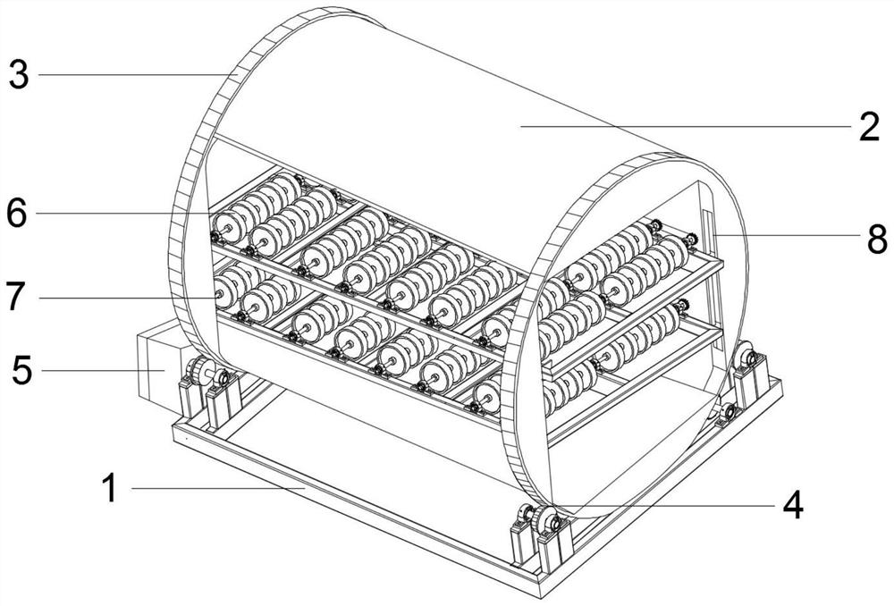
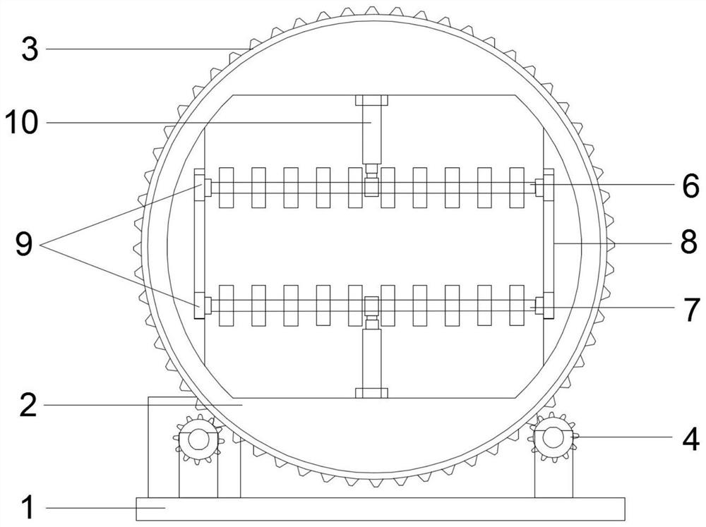
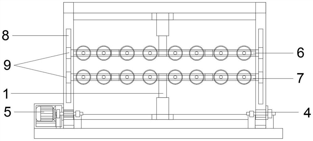
[0017] like Figure 1-Figure 4 As shown, the present invention provides a technical solution for an assembly line flipping device: an assembly line flipping device, the structure of which includes a base bracket 1, and a drum 2 is rotatably connected to the upper side of the base bracket 1, and two sides of the drum 2 are rotatably connected. The outer edge is fixed with an external gear ring 3, and the four corners of the base bracket 1 are respectively rotatably provided with limit gears 4, the limit gears 4 are arranged on the lower side of the drum 2, and the four limit gears 4 and The two outer gear rings 3 mesh with each other, one of the limit gears 4 is connected with a turning motor 5 at one end, and the inner side of the dr...


PUM


Abstract

The invention relates to the technical field of assembly line conveying equipment, in particular to an assembly line plate overturning device. The assembly line plate overturning device structurally comprises a base support. A roller is rotationally connected to the upper side of the base support. Outer tooth rings are fixedly arranged on the outer edges of the two sides of the roller. Limiting gears are rotationally arranged at the four corners of the base support correspondingly and arranged on the lower side of the roller. The four limiting gears are engaged with the two outer tooth rings.One end of one limiting gear is in shaft connection with a turning motor. A first roller frame and a second roller frame are connected to the inner side of the roller in a sliding manner. Sliding blocks are arranged on the two sides of the first roller frame and the two sides of the second roller frame. Sliding grooves used in cooperation with the sliding blocks are formed in the inner side of theroller. Electric push rods are arranged on the back sides of the first roller frame and the second roller frame. The two electric push rods are oppositely and fixedly arranged on the inner side of the roller, and the telescopic ends of the two electric push rods are connected with the first roller frame and the second roller frame correspondingly.

Description

technical field [0001] The invention relates to the technical field of assembly line conveying equipment, in particular to an assembly line flipping device. Background technique [0002] Plates are flat rectangular building material plates made of standard size, used in the construction industry, used as components of walls, ceilings or floors, or used in furniture decoration, including metal plates, wood plates or PC plates, divided into thin plates, medium plates Plates, thick plates, extra-thick plates, usually made into standard-sized flat rectangular building material plates, and as the plates are used in more and more fields, the existing plates need to be polished, colored, and solidified. Glue and other operations, and usually involve a large number of plates, so it needs to be processed through assembly line equipment during plate processing. Among them, the plate needs to be turned over during the assembly line processing operation. The turning process is mostly ma...

Claims


Application Information

Patent Timeline
IPC IPC(8): B65G13/00B65G13/12B65G47/248
CPCB65G13/00B65G13/12B65G47/248
Inventor 杨祝信
Owner 杨祝信
Learn More