Lubrication device, lubrication system, and vehicle

A technology for lubricating devices and oil outlets, which is applied to transmission parts, gear lubrication/cooling, belts/chains/gears, etc., and can solve problems such as increased power loss

Inactive Publication Date: 2020-10-20
ANHUI JIANGHUAI AUTOMOBILE GRP CORP LTD
View PDF3 Cites 0 Cited by
  • Summary
  • Abstract
  • Description
  • Claims
  • Application Information

AI Technical Summary

Problems solved by technology

[0004] The main purpose of the present invention is to provide a lubricating device, a lubricating system and a vehicle, aiming to solve the technical problem that the existing transmission lubricating system is required to ensure that all the gears in the gearbox are fully lubricated, resulting in increased power loss

Method used


Image

  • Lubrication device, lubrication system, and vehicle
  • Lubrication device, lubrication system, and vehicle
  • Lubrication device, lubrication system, and vehicle

Examples


Embodiment Construction

[0026] It should be understood that the specific embodiments described here are only used to explain the present invention, not to limit the present invention.

[0027] The following will clearly and completely describe the technical solutions in the embodiments of the present invention with reference to the accompanying drawings in the embodiments of the present invention. Obviously, the described embodiments are only some of the embodiments of the present invention, not all of them. Based on the embodiments of the present invention, all other embodiments obtained by persons of ordinary skill in the art without creative efforts fall within the protection scope of the present invention.

[0028] It should be noted that all directional indications (such as up, down, left, right, front, back...) in the embodiments of the present invention are only used to explain the relationship between the components in a certain posture (as shown in the accompanying drawings). Relative positi...


PUM


Abstract

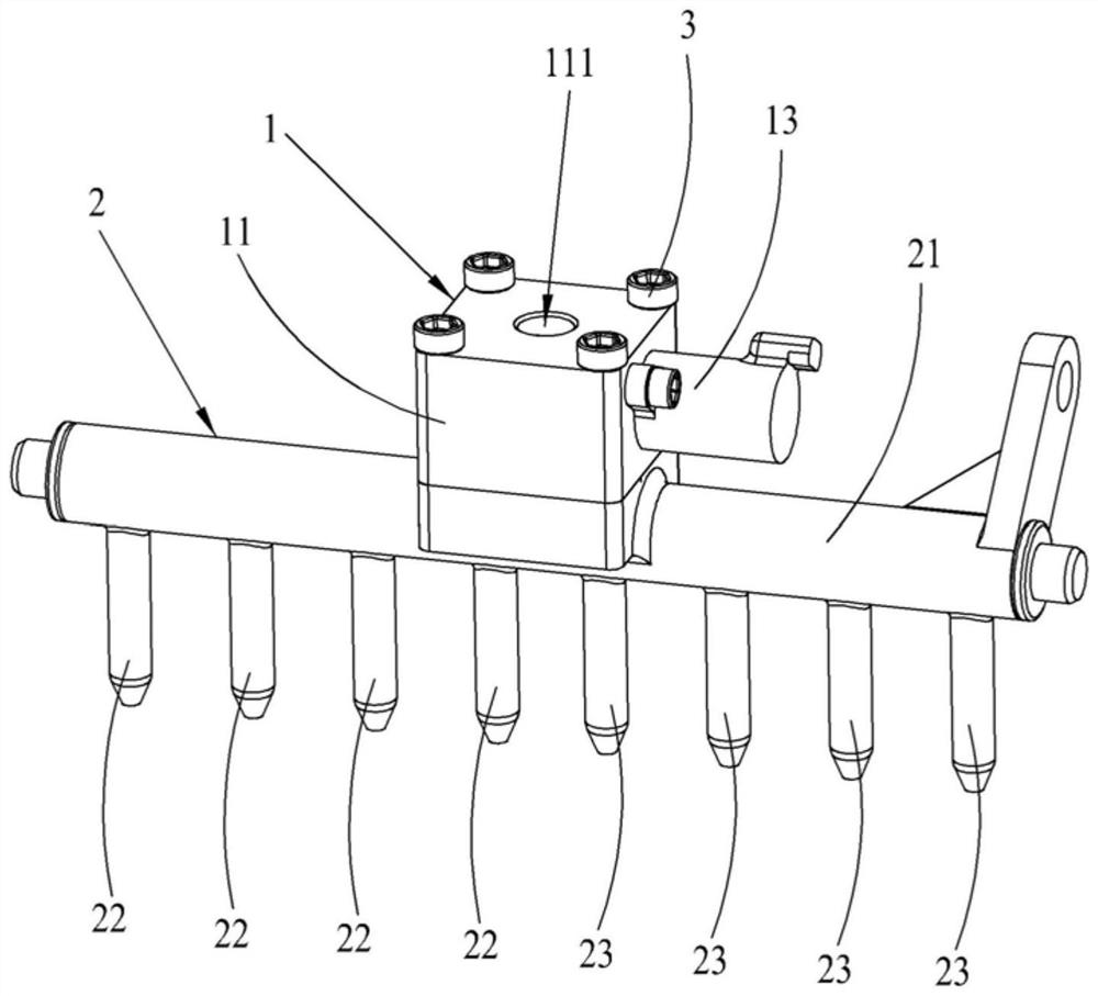
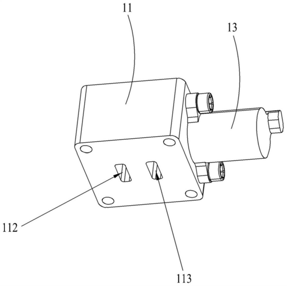
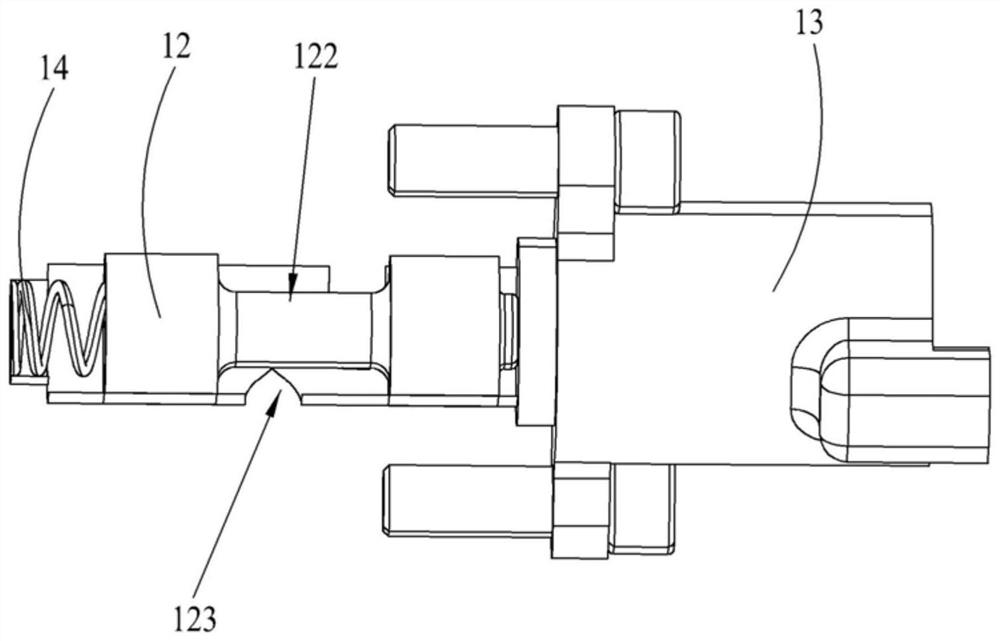
The invention discloses a lubrication device, a lubrication system, and a vehicle. The lubrication device includes a valve body assembly and an oil injection assembly, the valve body assembly includesan oil inlet shell body, and an oil inlet valve core, an oil inlet, a first oil outlet, and a second oil outlet are formed in the oil inlet shell body, and the oil inlet valve core is used to make the oil inlet communicate with the first oil outlet or the second oil outlet. The oil injection assembly is connected with the oil inlet shell body, a first oil injection channel communicating with thefirst oil outlet and a second oil injection channel communicating with the second oil outlet are formed on the oil injection assembly, the first oil injection channel separates from the second oil injection channel, the first oil injection channel is used to carry out oil injection on a plurality of first gears, and the second oil injection channel is used to carry out the oil injection on a plurality of second gears. According to the device, the system, and the vehicle, the oil inlet valve core is controlled to make lubricant flow to the first oil injection channel from the first oil outlet to carry out the oil injection on the first gears or flow to the second oil injection channel from the second oil outlet to carry out the oil injection on the second gears, the required oil supply flowis reduced, and the power loss is lowered.

Description

technical field [0001] The invention relates to the technical field of vehicle manufacturing, in particular to a lubricating device, a lubricating system and a vehicle. Background technique [0002] The function of the gearbox lubrication system of the automobile is to provide lubricating oil to the rolling or sliding parts of the gears and bearings inside the transmission, to ensure the fluid lubrication of the friction surfaces, reduce friction and wear, and cool the lubricating parts at the same time. In the current gearbox, the lubrication system mainly has two forms: splash lubrication and forced lubrication. Among them, forced lubrication refers to the use of a hydraulic pump to increase the pressure of the lubricating oil, and then spray the pressurized lubricating oil to the gearbox through the oil injection pipe. In order to ensure that all the gears are fully lubricated, the oil supply flow of the hydraulic pump must be guaranteed, which will easily lead to an incr...

Claims


Application Information

Patent Timeline
IPC IPC(8): F16H57/04
CPCF16H57/0404F16H57/0436F16H57/0456
Inventor 王中华郑海兵杨士先
Owner ANHUI JIANGHUAI AUTOMOBILE GRP CORP LTD
Why Eureka
Try Eureka