
Method an apparatus to control the starting procedure of an internal combustion engine

A technology of internal combustion engine and starting process, applied in the direction of internal combustion piston engine, combustion engine, engine control, etc., can solve the problem of increasing fuel, achieve the effect of improving vaporization, reducing emissions, and increasing vaporization

Inactive Publication Date: 2010-11-03
FORD GLOBAL TECH LLC
View PDF5 Cites 0 Cited by
  • Summary
  • Abstract
  • Description
  • Claims
  • Application Information

AI Technical Summary

Problems solved by technology

However, when the fuel contains ethanol and at low temperatures, this requires an increased fuel supply, which pushes the injection system to its design limits

Method used


Image

  • Method an apparatus to control the starting procedure of an internal combustion engine
  • Method an apparatus to control the starting procedure of an internal combustion engine
  • Method an apparatus to control the starting procedure of an internal combustion engine

Examples


Embodiment Construction

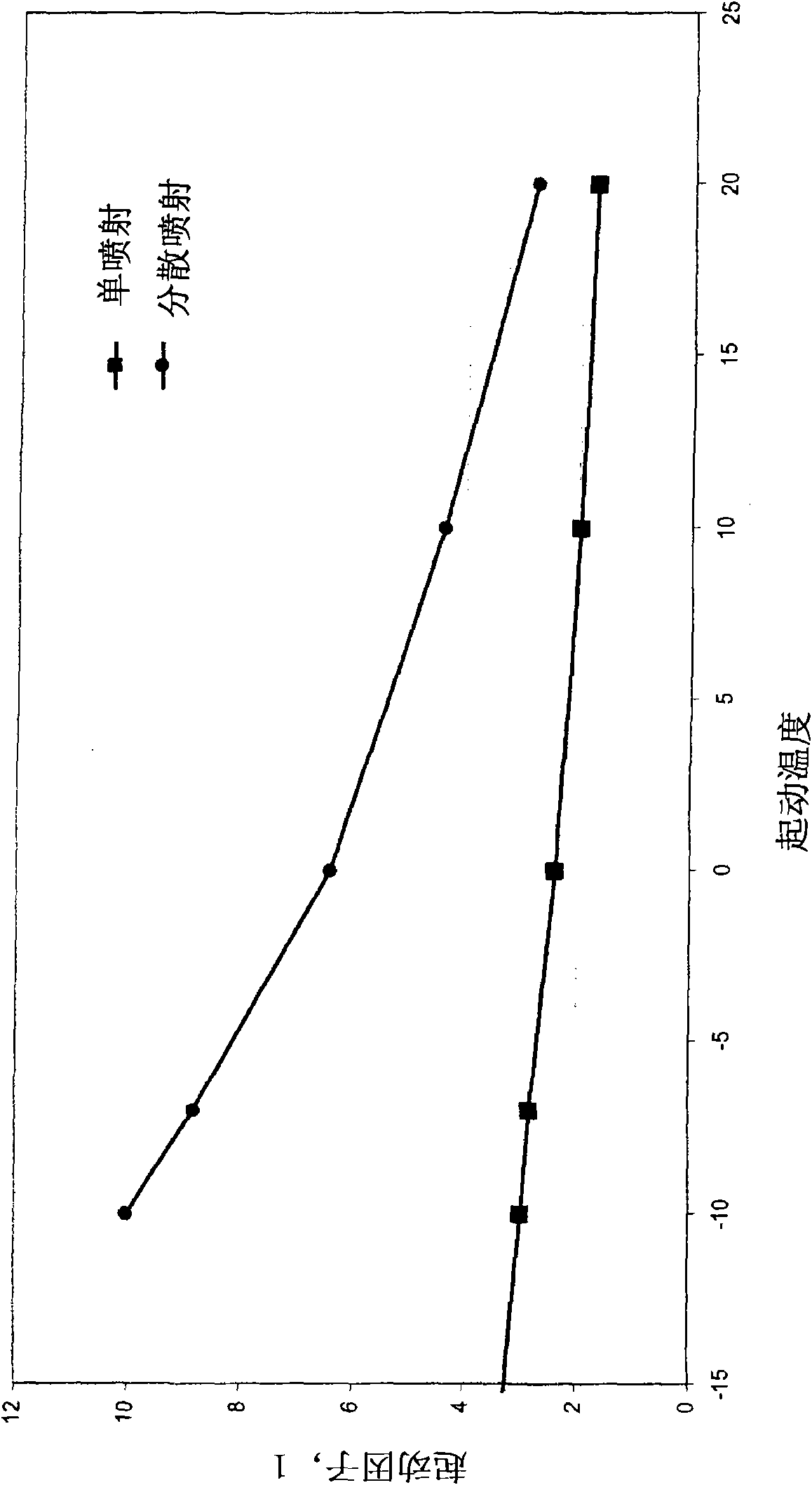
[0019] first reference image 3 Explain the problems mentioned in the introduction with the known "spread" injection mode when starting an internal combustion engine and at low temperatures. image 3 The curve for shows the so-called cranking factor, the excess growth of fuel injection required to achieve a sufficient amount of fuel vapor compared to the amount of fuel actually required for combustion purposes, plotted as a function of cranking temperature.

[0020] image 3 The upper curve of , shows the start factor for a typical split start regime, where the start of the first injection (SOI 1) occurs at a crank angle (CA) of 250° before top dead center (BTDC), and the end of the second injection (EOI 2) occurs at a crank angle of 60° before top dead center, the dispersion ratio (ratio of the first injection to the second injection) is from 40% to 60%, the ignition advance is 5°, and the E85 is used fuel.

[0021] With this type of dispersion, the following adjustment da...


PUM


Abstract

The invention relates to a method and an apparatus to control the starting procedure of an internal combustion engine. In the method for controlling the starting procedure, the lean air-fuel mixture is at least intermittently ejects the fuel into the compressed air.

Description

technical field [0001] The invention relates to a method and a device for controlling a starting process in an internal combustion engine. The invention may be advantageously used in conjunction with spark ignition engines having direct injection which enables stratified charge operation. Background technique [0002] In spark ignition engines, direct injection allows fuel to be introduced into compressed heated air. This provides more favorable conditions for the vaporization of fuels, especially alcohol fuels. However, in order to ensure that the internal combustion engine can be started at low temperatures, an excess fuel is usually supplied in a conventional cold start regime, combined with a direct injection spark ignition engine. However, such excess fueling is greatly increased, especially when ethanol / gasoline blends are used. Such excess fueling may cause problems arising from injection pressure drops. Heating of the excess fuel results in a further reduction in...

Claims


Application Information

Patent Timeline
Patent Type & Authority Applications(China)
IPC IPC(8): F02D41/06F02D41/30
CPCF02D41/3023F02D41/0025F02D41/062F02D41/3076F02D41/401F02D19/0655F02D2041/389Y02T10/30
Inventor H·鲁兰M·K·施普林格G·卢文T·洛仑兹
Owner FORD GLOBAL TECH LLC
Learn More