Auxiliary oil pump device for hybrid electric vehicle and control method

A hybrid vehicle and auxiliary oil pump technology, which is applied in hybrid vehicles, power units, pneumatic power units, etc., can solve the problems of clutches not opening and closing normally, oil pressure loss, and high oil pressure.

Pending Publication Date: 2021-01-29
荆州职业技术学院
View PDF0 Cites 0 Cited by
  • Summary
  • Abstract
  • Description
  • Claims
  • Application Information

AI Technical Summary

Problems solved by technology

[0005] In the current hybrid electric vehicle, the power clutch is realized through the wet clutch between the engine and the electric motor. The oil pressure of the wet clutch is provided by the mechanical oil pump driven by the electric motor. When the electric motor stops, the oil in the clutch will lose pressure, resulting in The clutch cannot be opened and closed normally. At present, the auxiliary oil pump is generally used for auxiliary pressurization. However, most of the current auxiliary oil pump devices use an external oil pump and an external electric motor for secondary pressurization. However, the control logic of the auxiliary oil pump is simple, generally After the motor stops, start the auxiliary oil pump to pressurize, but the main shaft will not stop immediately when the motor stops, and the oil pressure in the clutch will drop in a linear manner. If the auxiliary oil pump is directly started to pressurize, the oil pressure will be too high, and When the motor is started again, the oil pressure will be lost again, resulting in instability of oil pressure

Method used


Image

  • Auxiliary oil pump device for hybrid electric vehicle and control method
  • Auxiliary oil pump device for hybrid electric vehicle and control method
  • Auxiliary oil pump device for hybrid electric vehicle and control method

Examples


Embodiment Construction

[0035] The present invention will be further described below in conjunction with the accompanying drawings, but the protection scope of the present invention is not limited to the following description.

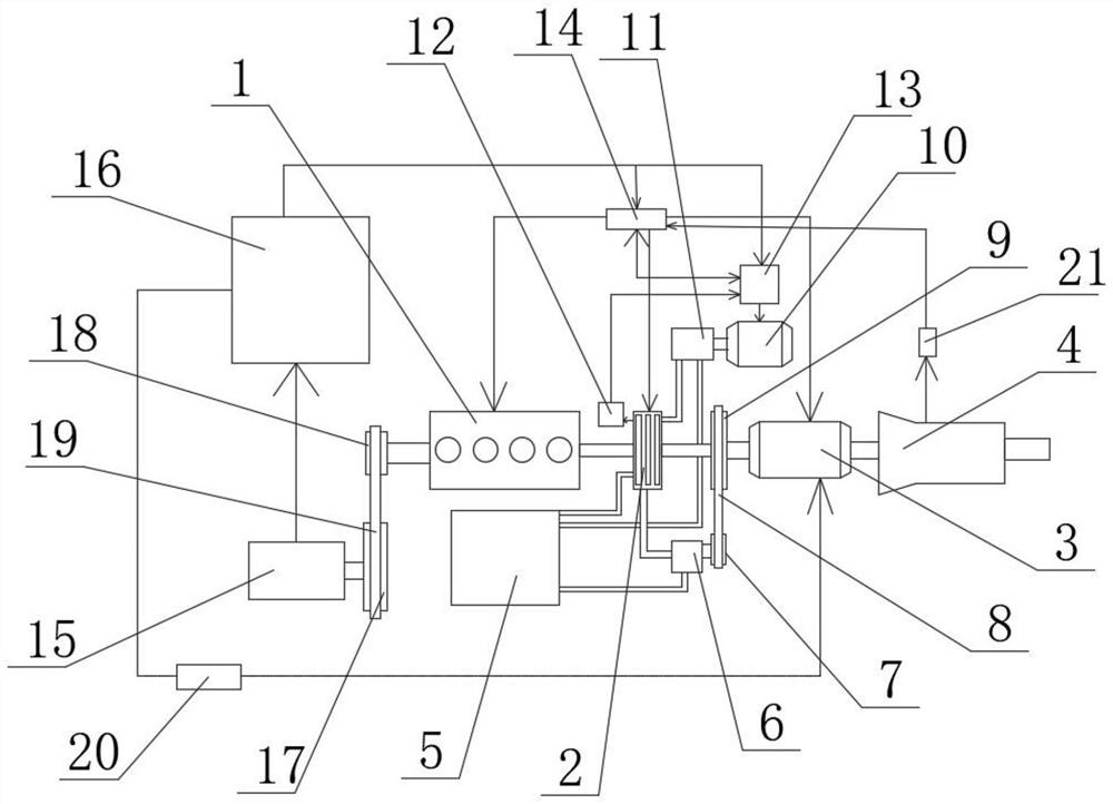
[0036] Such as Figure 1 to Figure 2As shown, an auxiliary oil pump device for a hybrid vehicle includes an engine 1 and an electric motor 3, the output end of the engine 1 side is fixedly connected with a clutch 2, and the input end of the clutch 2 away from the engine 1 side is connected with the electric motor 3 The output end on the side is fixedly connected, the side of the motor 3 away from the clutch 2 is provided with a gearbox 4, and the input end of the gearbox 4 is fixedly connected to the output end of the motor 3 away from the side of the clutch 2;

[0037] The output end of the motor 3 close to the clutch 2 is fixedly connected with the first driving transmission wheel 9, the outer surface of the first transmission wheel 9 is connected with the first transmissio...


PUM


Abstract

The invention relates to the technical field of automobile auxiliary oil pumps, and in particular relates to an auxiliary oil pump device for a hybrid electric vehicle and a control method. The auxiliary oil pump device comprises an engine and a motor, the output end of one side of the engine is fixedly connected with a clutch, the input end of the side, away from the engine, of the clutch is fixedly connected with the output end of one side of the motor, and a gearbox is arranged on the side, away from the clutch, of the motor. The auxiliary oil pump device has the advantages that the stepless speed regulation motor, the auxiliary oil pump and a power regulator are arranged, an oil pressure sensor is arranged on one side of the clutch, the pressure sensing end of the oil pressure sensor is located in the clutch, and the electric signal output end of the oil pressure sensor is electrically connected with the signal input end of the power regulator; and the situation that when oil pressure in the clutch is lost slowly, oil supply of the auxiliary oil pump is too fast, pressure is too large, the oil pressure in the clutch is lost rapidly, oil supply of the auxiliary oil pump is too slow, oil pressure loss is too much, and the clutch cannot be used normally is prevented.

Description

technical field [0001] The invention relates to the technical field of automobile auxiliary oil pumps, in particular to an auxiliary oil pump device and a control method for hybrid electric vehicles. Background technique [0002] In a broad sense, a hybrid vehicle refers to a vehicle whose drive system is composed of two or more single drive systems that can operate simultaneously. [0003] The so-called hybrid vehicles generally refer to gasoline-electric hybrid vehicles, which use traditional internal combustion engines (diesel engines or gasoline engines) and electric motors as power sources, and some engines have been modified to use other alternative fuels, such as compressed natural gas, propane and ethanol. fuel etc. [0004] With the increasingly stringent environmental protection measures around the world, hybrid vehicles have become a focus of automotive research and development due to their energy-saving and low-emission characteristics, and have begun to be comm...

Claims


Application Information

Patent Timeline
IPC IPC(8): B60K6/387B60W10/02B60W10/06B60W10/08B60W10/10
CPCB60K6/387B60W10/02B60W10/06B60W10/08B60W10/10Y02T10/62
Inventor 宋健
Owner 荆州职业技术学院
Why Eureka
Try Eureka